
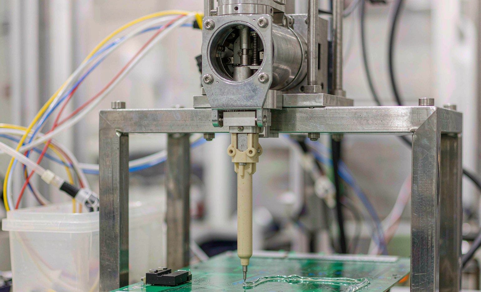
A dispense valve is a small machine that does one thing badly for a living: it holds a reactive fluid under pressure, meters it in microlitres, and then sits still for twenty seconds with that same fluid curing against every wetted surface. The seal is the part that has to survive both halves of that cycle — the pressure stroke and the idle soak — for millions of cycles, with no lubricant film to help it and no access for inspection.
Most failed dispensing seals we see in returned valve bodies are not worn out. They are swollen, extracted, bonded, or abraded by the fluid they were supposed to contain. A nitrile O-ring in an acetone-thinned coating will absorb enough solvent in a week to grow past its groove and start shaving itself on the stem. A silicone seal in a silicone adhesive line will dissolve into its own chemistry. An FKM seal in a two-part epoxy with an amine hardener will harden, crack, and leave crumbs in the mix chamber.
This guide works backwards from the adhesive. It maps nine fluid families against five seal materials, gives the swell and temperature numbers you can design against, and closes with the specification routine we use when a dispenser OEM sends us a valve body and a fluid data sheet.
The Dispense Valve Is the Hardest Seal Job in the Plant
Compare a dispense valve seal with a hydraulic cylinder rod seal, which is the application most seal catalogues are written around. The hydraulic seal runs in oil, at a steady temperature, with a film of lubricant between the lip and the rod, and a wiper keeping grit out. Its failure mode is extrusion or lip wear after a long life.
The dispense valve seal runs in a fluid chosen for how aggressively it crosslinks, at ambient or hot-melt temperature, usually dry, often after a solvent flush that changes the chemistry completely. Its duty cycle is short and repetitive: 0.2 seconds of pressure, 20 seconds of dwell, 500,000 times a year. And the fluid it holds is frequently the same fluid used to bond elastomers to metal.
Set the two side by side and the specification logic reverses. The hydraulic seal’s fluid is designed to lubricate; the dispense seal’s fluid is designed to bond. The hydraulic seal runs 40–80°C at a steady temperature; the dispense seal runs anywhere from 20°C to 200°C depending on whether the line is laying down a cyanoacrylate or a polyolefin hot melt. The hydraulic seal sees one chemistry for its whole life; the dispense seal sees adhesive, then purge solvent, then cleaner, then adhesive again, four times a shift.
Failure signatures diverge the same way. Hydraulic seals die by extrusion and lip wear — slow, visible, and scheduled. Dispense seals die by swell, extraction, bonding, and abrasive wear, and the first symptom is usually a 3–5% shift in shot weight that the operator corrects by trimming dispense time. By the time the valve is pulled for service, the stem is scored and the body is scrap.
Five Mechanisms That Kill a Wetted Seal
Almost every dispensing seal failure resolves into one of five mechanisms. Naming the mechanism correctly is most of the diagnosis; the material choice follows from it.
| Mechanism | What you see on the bench | What is happening in the polymer | Direction of fix |
|---|---|---|---|
| Swelling | Seal is soft, enlarged, will not sit in the groove; stem drags | Solvent molecules enter the network; volume grows 15–50% | Change polymer family, not hardness |
| Extraction | Seal shrinks, hardens, surface looks chalky; leaks on cooldown | Plasticiser and low-molecular-weight fractions leach into the fluid | Peroxide-cured or higher-purity compound; post-cure |
| Chemical attack | Cracks, blisters, sticky surface, hard crust | Dehydrofluorination by amines, or backbone scission by strong oxidisers | FFKM, PTFE, or a barrier design |
| Adhesion / cure-in-place | Seal bonded to the stem; tear on actuation | Cyanoacrylate or epoxy polymerises against the elastomer surface | Non-stick wetted material: PTFE, UHMWPE, coated metal |
| Abrasive wear | Flat spot, groove-shaped scar, black slurry in the fluid | Silver, ceramic, or thermal fillers grinding the seal against the stem | Harder, lower-friction material; surface finish on the stem |
Two of these are frequently misdiagnosed. Extraction looks like “the seal dried out” and gets fixed by relubricating, which only postpones it. Adhesion looks like “the seal tore” and gets fixed by buying a tougher elastomer, which bonds even harder. Both need a different surface, not a stronger one.
Start With the Adhesive Chemistry, Not the Seal
The useful sorting question is not “what material is best” but “what does this fluid do to a hydrocarbon chain”. Adhesive families sort cleanly once you ask that.
Cyanoacrylate: The Adhesive That Becomes a Fastener
Cyanoacrylate cures by anionic polymerisation triggered by surface moisture, in seconds, with no solvent and no heat. It also bonds most elastomers extremely well — which is the whole problem. A nitrile or FKM O-ring sitting in a cyanoacrylate valve will bond to the stem within a few dwell cycles, and the actuator will then tear the seal instead of moving it.
The wetted materials that work here are the ones cyanoacrylate cannot wet: PTFE, filled PTFE, and UHMWPE, plus coated stainless. Practical valves use a PTFE or UHMWPE diaphragm or a PTFE-encapsulated O-ring, with the elastomer core doing the sealing and the fluoropolymer doing the contact. On the air side, NBR at 70 Shore A is fine — it never sees the fluid.
Moisture control is part of the seal specification. Cyanoacrylate cure rate tracks ambient humidity, so a valve that runs clean at 35% RH can bond shut at 65% RH in the same room, with the same seal. If your line is in a humid climate and the failure appeared in the rainy season, the seal was not the variable.
UV-Cure and Anaerobic Acrylates
Acrylate systems — UV-curable, anaerobic, and light-cure hybrids — are the most aggressive common fluid a dispense seal meets. They carry reactive acrylate monomers and oligomers that swell nitrile in days and attack standard FKM over weeks. Anaerobic grades add metal-ion cure initiation, so any seal running against a steel stem sits in the worst possible contact geometry.
FFKM is the default here, and it is not a marketing answer: perfluoroelastomer backbones resist acrylate monomers where FKM’s partially fluorinated backbone does not. The caveat is that FFKM compatibility is compound-specific. A general-purpose FFKM selected for acid service and a grade formulated for acrylate and solvent exposure behave differently, and the difference shows up as a 15% versus a 3% swell after 168 hours. Ask for the compound data sheet, not the family name.
Where the geometry allows it, a spring-energised PTFE lip seal outperforms any elastomer in acrylate service: the PTFE jacket is inert, and the metal spring supplies the load the polymer cannot. Our spring-energised seal range covers the small cross-sections these valves use.
Two-Part Epoxy and Amine Hardeners
Epoxy is two fluids with opposite demands, and this is where single-material answers break down. The resin side is a moderately aggressive organic mixture that most FKM compounds handle. The hardener side is an amine, and amines are exactly what attacks FKM: the base strips hydrogen fluoride from the backbone, leaving a hard, cracked, brittle surface. Standard FKM in a static mix block fed from the hardener side will fail in weeks.
The fix is FFKM on the hardener side, or EPDM where the hardener is the only fluid contact and temperature stays moderate — EPDM is one of the few elastomers that tolerates amines well. Do not carry that EPDM choice over to the resin side: EPDM swells badly in aromatic and aliphatic hydrocarbons.
Mix blocks and static mixers deserve separate attention. The seal at the mixer inlet sees the blended fluid, which is more aggressive than either component, and it sees it at the moment the reaction starts. A 2K meter-mix machine that runs epoxy should have FFKM at every wetted joint downstream of the mix point, and a documented purge routine for shutdowns longer than the pot life.
Polyurethane, Isocyanate and Moisture-Cure Systems
Isocyanate-based adhesives — polyurethane reactive hot melts, 2K PU, and moisture-cure PU — are moisture-sensitive by design. They also attack EPDM, which rules out the cheapest amine-resistant option. FKM at 70–75 Shore A handles most PU systems at moderate temperature; FFKM is the safer answer where plasticisers or solvents are also present, since plasticiser extraction is the usual cause of PU-line seal hardening.
Cured PU residue is another abrasion source. A seal that runs against partially cured PU picks up a film that hardens on the surface and then acts as a grinding paste. Wetted parts benefit from a low-friction finish — filled PTFE or a polished, passivated stem — more than from a harder elastomer.
Silicone Sealants: The One Case Where the Obvious Material Is Wrong
Silicone sealants and silicone oils dissolve silicone rubber. Same-family contact means the fluid migrates into the seal network and the seal migrates into the fluid, so you get a swollen seal, a contaminated product, and a permanent tacky film on the valve body.
Use FKM, FFKM, or PTFE for silicone dispensing, and specify platinum-cured silicone only on the air side where no fluid contact exists. The same rule applies in reverse for silicone-based thermal gels: they will find any silicone seal in the fluid path.
Hot Melt: 120 to 200°C and No Solvent to Blame
Hot melt removes the solvent question and replaces it with a temperature one. EVA and polyolefin hot melts run at roughly 150–200°C at the nozzle; reactive PUR runs cooler, around 120–150°C, but cures by moisture afterwards, so the seal sees both heat and a crosslinking fluid. Cured PUR residue is also extremely hard to remove without damaging the seal.
FKM covers the lower half of that range comfortably and the upper half briefly. Above about 200°C, or wherever the seal sits close to the heater cartridge, FFKM or a PTFE/spring-energised combination is the durable answer. Thermal expansion is the second design variable: an aluminium body and a steel stem move differently over a 180°C swing, and a seal sized at room temperature can lose its squeeze at operating temperature. Groove depth should be checked at the hot condition, not the bench condition.
Filled Adhesives: Silver, Ceramic and Thermal Pastes
Electrically conductive and thermally conductive adhesives carry 60–85% filler by weight — silver flake, boron nitride, alumina, graphite. These are abrasive slurries, not fluids, and the seal failure is mechanical: a flat worn on the O-ring, a polished scar on the stem, and grey sludge in the mix chamber.
Abrasion resistance in this service comes from polyurethane at 90–95 Shore A, filled PTFE, or UHMWPE — not from a harder rubber. A 90 Shore A FKM O-ring will resist extrusion better than a 70 Shore A one but will still wear flat, because hardness does not equal abrasion resistance. Where the seal is static and the wear is on the stem, moving the wear to a replaceable PTFE or UHMWPE component is cheaper than upgrading the elastomer.
| Adhesive / fluid family | Best wetted seal material | Acceptable with limits | Avoid | Primary risk |
|---|---|---|---|---|
| Cyanoacrylate | PTFE, UHMWPE, PTFE-encapsulated | Coated stainless (no elastomer wetted) | NBR, FKM, EPDM (all bond) | Cure-in-place bonding |
| UV-cure acrylate | FFKM (acrylate grade) | Spring-energised PTFE | NBR, EPDM, standard FKM | Swell, then hardening |
| Anaerobic methacrylate | FFKM | PTFE capsule over FKM core | NBR, silicone | Metal-contact cure, bonding |
| 2K epoxy — resin side | FKM 70–75 A | FFKM for solvent-thinned grades | EPDM | Solvent swell |
| 2K epoxy — amine hardener | FFKM | EPDM (moderate temperature only) | Standard FKM | Dehydrofluorination, cracking |
| Polyurethane / isocyanate | FKM 70–75 A | FFKM where solvents present | EPDM | Plasticiser extraction, hardening |
| Silicone sealant / gel | FKM, FFKM, PTFE | — | Silicone rubber (VMQ) | Same-family dissolution |
| Hot melt EVA / polyolefin | FKM to 200°C; FFKM above | PTFE at the hot face | NBR, EPDM | Heat aging, extrusion at temperature |
| Silver / ceramic filled paste | PU 90–95 A, filled PTFE, UHMWPE | 90 A FKM for static joints | 70 A NBR | Abrasive wear |
Reading Swell Numbers the Way a Designer Does
Every compound data sheet quotes volume swell from ASTM D471. Three reading rules separate a usable number from a marketing number.
Read the temperature. A 168-hour immersion at 23°C tells you very little about a valve that runs at 70°C. Swell is strongly temperature-dependent: an FKM compound that grows 6% in toluene at room temperature can grow 10% at 70°C in the same 168 hours. Test at the service temperature, or derate the room-temperature figure by roughly half again.
Convert volume to linear. Swell is quoted by volume, but grooves are cut by linear dimension. Volume change converts to cross-section change by the cube root: 15% volume swell is about a 4.8% increase in cross-section, 30% is about 9.1%, 50% is about 14.5%. That number is what consumes your squeeze.
Do the squeeze arithmetic. Take a 3.53 mm cross-section O-ring in a groove giving 18% squeeze — 0.64 mm of interference. A fluid that swells the compound 30% by volume adds 0.32 mm to the cross-section, half the squeeze, and the seal now leaks at low pressure while dragging at high pressure. A 50% swell eats 0.51 mm and the joint is done. This is why “15% swell after 168 hours” is the working limit for a dynamic seal and 25% is roughly the limit for a static one.
Groove fill is the second constraint. A swollen seal needs somewhere to go. Static grooves should not exceed 85–90% fill; dynamic grooves should stay at 75–85%. If the groove is already at 88% fill with a dry seal, a compound with 12% swell has no room and will extrude into the clearance.
Where the Seal Sits Changes the Answer
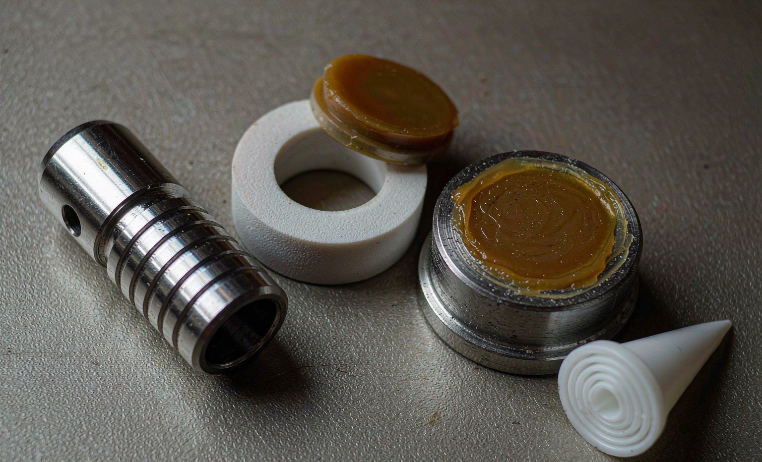
Two seals in the same valve body can need different materials, and often do.
A static face seal under a fluid manifold sees the fluid but no motion. It tolerates higher swell, higher hardness, and a plain O-ring or gasket. A dynamic stem seal sees the same fluid plus 500,000 strokes, so it needs low friction, abrasion resistance, and a swell budget half as generous. A diaphragm separates fluid from air entirely: the fluid side is a barrier material question, the air side is a plain NBR question. A shaft seal on the pump that feeds the valve sees continuous rotation and heat from the motor, which is a rotary lip seal problem, not a valve problem.
The practical consequence is that a “seal kit” for a dispense valve is rarely one compound. When we quote a kit for a 2K epoxy dispenser, the hardener-side seals are FFKM, the resin-side seals are FKM, the air-side seals are NBR, and the wetted diaphragm is PTFE-faced. Buying the kit as a single material to save cost is how a valve ends up leaking from the cheapest joint in the assembly.
Seal Profiles Used in Dispensing Hardware
Profile choice follows from the motion and the cleanability requirement, and each profile has a hard limit.
| Profile | Where it fits | Strength | Limit |
|---|---|---|---|
| O-ring in a rectangular groove | Static joints, manifold faces, nozzle retainers | Cheapest, widest size coverage, AS568 and metric | No dynamic scraping action; rolls and twists in long strokes |
| PTFE-encapsulated O-ring | Static joints in aggressive fluid | Fluoropolymer skin with elastomer core; near-inert wetted face | Not for dynamic service; skin damaged by sharp groove edges |
| U-cup / lip seal | Reciprocating stems and plungers | Pressure-energised lip, good scrape on the return stroke | Needs a lead-in chamfer; lip folds on installation if stretched |
| Spring-energised PTFE lip | High-cycle stems, acrylate and solvent service | Inert jacket, metal spring load, low friction, wide temperature | Higher cost; requires a hard, fine-finished mating surface |
| Diaphragm | Miniature valves, UV and cyanoacrylate | No sliding contact, no dead volume, no stem packing | Stroke-limited; fatigue life falls fast with increasing stroke |
| Flat gasket / bonded washer | Nozzle seats, cartridge valve bases | High unit load, cheap, replaceable | One-time compression; no recovery after thermal cycling |
Mating surface finish matters more in dispensing than in hydraulics, because there is no oil film to hide it. A 0.4 µm Ra stem in a spring-energised PTFE seal will give years of service; the same seal on a 1.6 µm turned surface will wear through the jacket in months. We cover the groove-side equivalent in the note on why groove surface finish determines seal life.
Cure-in-Place: The Failure That Looks Like a Seal Failure
The most expensive dispensing seal failures are not chemical at all. They are process failures that present as seal failures.
Cyanoacrylate left in a closed valve over a weekend will cure against the stem and bond the seal in place. Epoxy left in a static mixer past its pot life will set into a plug that shears the seal on the next actuation. UV adhesive in a valve body with a transparent window will cure on the seal face wherever light reaches it. In each case the seal is destroyed by the fluid curing in the wrong place, and the fix is a purge routine, not a different compound.
Three rules cover most of it. Flush with a solvent that is compatible with the seal, not just with the adhesive — MEK will clear epoxy and will also swell an FKM seal 30–50%. Purge before every shutdown longer than the pot life, not just at shift end. And on valves that cannot be flushed, use a diaphragm design with no dead volume, so there is nowhere for fluid to sit.
Cleanout Chemistry Is Half the Specification
A seal that is compatible with the adhesive and incompatible with the cleaning solvent still fails, and the failure gets blamed on the adhesive. This is common in plants that switch from an acetone flush to MEK, or add an NMP-based cleaner for environmental reasons.
Build the compatibility table around both fluids. FKM handles aromatic and aliphatic hydrocarbons well but swells 30–50% in acetone and MEK. EPDM handles ketones, alcohols, and water but not hydrocarbons. FFKM covers both, including ketones, esters, and amines, at a cost multiple. PTFE covers everything chemically and brings cold flow and a manufacturing cost of its own.
The cleanest solution in high-mix plants is often a spring-energised PTFE seal: one part number that survives adhesive and solvent changes without requalification. For plants running a single adhesive family on a dedicated line, the elastomer route stays cheaper and seals better.
A Six-Step Specification Routine
This is the sequence we run when a dispenser OEM or a contract manufacturer sends a valve body for a seal quote.
1. List every fluid the seal touches, in order. Adhesive A, purge solvent B, cleaner C, and the residue that forms when A meets B. The residue is usually the most aggressive thing in the list.
2. Fix the temperature window at the seal, not at the nozzle. A hot melt set to 170°C at the nozzle may be 140°C at the seal and 190°C during a heater overshoot. Specify the maximum the seal sees, plus 20°C.
3. Classify the motion. Static, reciprocating, rotary, or diaphragm flexure. This eliminates half the candidate profiles immediately.
4. Set the swell budget. 15% volume for dynamic, 25% for static, then check groove fill with the swollen cross-section, not the nominal one.
5. Choose material by fluid family, then verify by compound. The family name narrows the field; the specific compound data sheet decides. Insist on 168-hour immersion data in your actual fluid at your actual temperature — a compound supplier can usually run it in two weeks.
6. Specify the interface. Stem finish, groove finish, lead-in chamfer, and hardness of the mating metal. Half of the failures we investigate trace back to a 1.6 µm stem or a sharp groove edge, not to the compound.
What to Put on the Purchase Order
Seals for dispensing equipment are usually small-volume, high-mix orders, which makes a vague purchase order expensive for both sides. The order should carry the compound designation and cure system, the hardness with tolerance, the dimensional standard and tolerance class, the relevant compliance documents, and the cleaning chemistry the part must survive.
For silicone-free or PFAS-free programs, say so explicitly and expect a material declaration rather than a verbal confirmation: a “silicone-free” claim can fail on a mold release agent, and a PFAS statement now needs to cover PTFE parts separately from fluoroelastomer parts. The PTFE, PEEK, and UHMWPE components that usually accompany these seals come from our machined plastics line, and both are frequently ordered together through the customized products route.
Two reference points are worth keeping on file for the material conversation. Hallite’s technical library documents thermoplastic seal behaviour under load, and Trelleborg’s sealing solutions catalogue publishes fluid compatibility data by compound family. For an independent view of how compound chemistry drives swell, Darcoid’s material pages and ERIKS’s sealing technical manual are both useful, and PPE stocks the small-cross-section O-rings these valves use.
Key Takeaways
- Adhesive chemistry decides the seal material, not the other way round. Sort by fluid family first, then by compound.
- Cyanoacrylate fails seals by bonding, not by swelling. PTFE and UHMWPE are the wetted materials that survive it.
- Amines in epoxy hardeners attack standard FKM. Use FFKM on the hardener side, or EPDM where temperature allows.
- Silicone fluid and silicone rubber dissolve each other. Never put a VMQ seal in a silicone adhesive line.
- Convert volume swell to cross-section growth with the cube root, then subtract it from your squeeze: 30% swell costs about 0.32 mm on a 3.53 mm O-ring.
- 15% volume swell is the working limit for dynamic seals, 25% for static ones, and groove fill must be checked with the swollen dimensions.
- Purge discipline prevents more failures than material upgrades. Cured adhesive in a closed valve destroys any seal.
- Specify the compound, the cure system, the interface finish, and the cleaning solvent — a valve kit is rarely a single material.
If you are qualifying a seal for a specific adhesive, send us the fluid data sheet, the valve drawing, and the cleaning chemistry. We will come back with a compound recommendation, a swell estimate for your temperature, and a sample lot for line trial. Start from the rubber O-ring and X-ring range or the encapsulated seal range, and we will match the rest of the kit to it.
Wetted-Path Seals for Adhesive and Solvent Duty
Dispense valves ask for the narrow end of the compound range, and that is where our stock sits: FFKM and FKM O-rings and X-rings, PTFE and filled-PTFE seats and bushings, UHMWPE and PEEK wear parts, EPDM and silicone where the chemistry allows, plus encapsulated seals for the positions where a rubber core has to be shielded from the fluid.
The routine in this article is the one we run on incoming enquiries: adhesive chemistry first, then the wetted position, then the cleanout solvent, then temperature. Swell is read at the service temperature rather than at 23 °C, and cure-in-place risk is checked against the dead volume around the seal — a groove that traps two drops of catalysed adhesive will fail whatever the compound.
Send the fluid data sheet, the valve drawing and the cleaning chemistry to sales@bosssealing.com, and we will come back with a compound recommendation, a swell estimate at your temperature and a sample lot for line trial. The review costs nothing and the quote follows within a day; the contact form reaches the same desk.