
A twisted O-ring is a failed O-ring with a delay timer attached. The ring goes in looking fine, seals through commissioning, and then spiral failure — the characteristic helical crack that follows the ring’s circumference — opens a leak path weeks or months later, usually after the machine has shipped. Installation twisting is among the most cited causes of O-ring field failure, and unlike chemistry or temperature problems, it costs nothing to prevent: clean parts, the right lubricant, a tool that cannot cut, and a feeding technique that keeps the ring’s cross-section relaxed. This article is the procedure we give customers receiving our O-rings for the first time, in the order an assembly tech actually works.
Why a Twist Kills the Seal
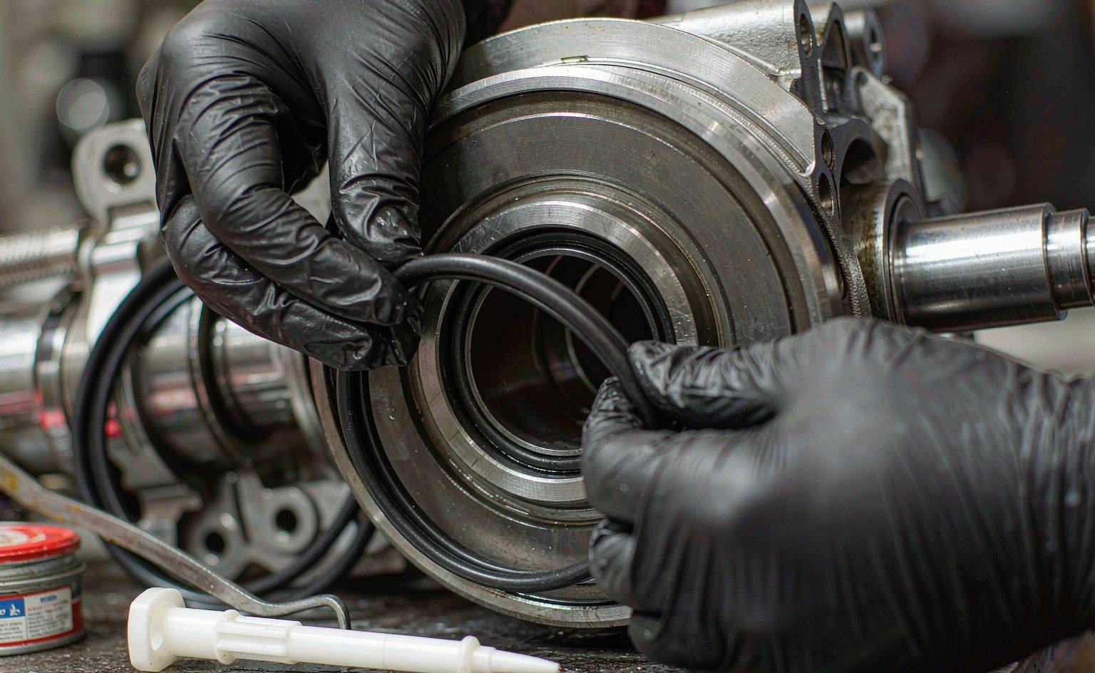
An O-ring seals because its compressed cross-section pushes back against the gland walls with uniform contact stress. A ring installed with a twist carries that stress unevenly: the twisted segment is stretched on one side and folded on the other, and the fold stores torsional stress in the rubber. Under pressure cycling, thermal cycling and vibration, the ring slowly rotates in its groove, the fold propagates, and the crack that follows the helix becomes the leak path. On a dissected failure this is unmistakable — the crack wraps the ring like a barber pole, on a plane roughly 45° to the cross-section.
Twisting happens three ways. It happens during installation, when the ring rolls down a shaft or gets dragged around a groove with high friction. It happens from gland geometry — a groove too wide lets the ring shift and fold under pressure pulses; excessive stretch reduces the cross-section and makes the ring unstable. And it happens from assembly habits: re-seating a ring that “didn’t look right” by rolling it with a fingernail is how many twisted rings are born at the bench. The fix list below addresses all three, in the order they occur.
Step 1: Prepare the Groove and Inspect the Ring
Friction is what turns a sliding ring into a rolling ring, and contamination is the main friction source. Wipe the groove, the mating faces and any lead-in chamfer with a lint-free cloth and a compatible solvent; a single metal chip under the ring both creates a leak path and forces the ring to ride over it, which is itself a twist trigger. Check the groove bottom corners while you are there — fillets of R0.2–0.5 mm are the standard recommendation, and a sharp corner does double damage: it cuts the ring at installation and concentrates stress afterward.
Inspect the ring itself before it goes anywhere near the groove. Look for nicks, flash, pocks and flattened sections, and run the ring between clean fingers — a nick you can feel with a gloved fingertip will leak. Never install a ring that was stored kinked or hung on a nail; the permanent set in a kinked ring cannot be pressed out by the gland. For the same reason, rings should come to the bench in their packaging, not loose in a parts tray where they pick up grit and deform each other.
Step 2: Lubricate With a Compatible Grease — Not Just Any Grease
Lubrication is the twist prevention mechanism, not a nice-to-have. A thin, uniform film on the ring and every surface it will slide across drops installation friction enough that the ring deforms instead of rolling. “Thin” matters: a glossy coat, not a dripping one. Excess grease collects in the gland, can clog ports and sensor passages, and in gas service it becomes its own contamination source.
Compatibility is where assemblies actually get damaged. The wrong lubricant does not just fail to help — it attacks the ring. Petroleum-based greases swell and degrade EPDM; silicone grease is wrong for oxygen service and is a contamination concern near bake-outs; and FFKM rings in process tools should get PFPE grease, not ordinary silicone, for cleanliness reasons. The table below is the shop-floor version we ship with product.
| O-ring compound | Use this lubricant | Never use | Why |
|---|---|---|---|
| NBR / HNBR | Petroleum grease, silicone grease | Nothing common — verify with exotic fluids | NBR tolerates petroleum base oils |
| EPDM | Silicone grease, glycerin-based soap | Any petroleum grease or oil | Petroleum products swell and soften EPDM within hours |
| FKM | Silicone grease (non-plasma duty), PFPE grease | Petroleum grease on hot or fuel duties | Base-oil compatibility and temperature drop at the film |
| FFKM (process tools) | PFPE grease only | Silicone grease | Silicone contamination survives bake-outs; PFPE is process-clean |
| Silicone (VMQ) | Silicone grease | Petroleum grease | Petroleum base oils attack silicone rubber |
One more rule that saves arguments on the floor: when in doubt, a small amount of the system’s own working fluid is usually a safe assembly lubricant for hydraulic and pneumatic assemblies — provided the fluid is clean, filtered and compatible with the compound. Grease that is “chemically compatible and does not clog anything downstream” beats improvised fluids, but improvised clean fluid beats petroleum grease on EPDM every time.
Step 3: Use Tools That Cannot Cut, and Shields Where the Ring Must Travel
The classic bench injury is a ring dragged across a thread, keyway or port edge with a screwdriver “helping.” Any sharp metal edge — including the edge of a worn pick — slices the rubber in a line too fine to see, and that line is a crack starter under pressure. The correct toolkit is deliberately blunt: plastic or brass O-ring picks, installation cones and sleeves with polished, chamfered leads, and nothing sharper than a fingernail shape.
Where the ring must cross a hazard it cannot avoid — a threaded rod end, a splined shaft, a port opening mid-path — shield the hazard. An installation cone over a thread, a smoothed sleeve over a spline, or a wrap of smooth tape over a sharp shoulder gives the ring a continuous sliding path. Masking tape is acceptable as a temporary shield as long as its adhesive never touches the ring; adhesive residue becomes a friction point and a contamination source.
Step 4: Feed the Ring — Never Roll It
This is the step where twisting is actually prevented. The rule: the ring slides, it does not roll. On a piston-groove installation, seat the ring into the groove first, then slide the whole piston into the bore — the gland is the ring’s home, and the less distance the ring travels unprotected, the less chance it has to twist. Never spin the ring down a shaft like a nut; each rotation it makes on the way down is a stored twist.
Keep stretch under control while feeding. Installation stretch up to about 50% is acceptable for getting over flanges, but once the ring is seated in the gland the installed stretch should be no more than roughly 5% — beyond that the cross-section thins, the seal force drops below design, and the ring has spare slack that pressure pulses will happily twist. If a ring needs violent stretching to reach its groove, the size is wrong; fix the size, not the technique.
Step 5: Verify Before Close-Out
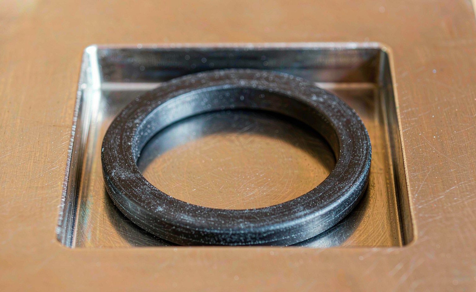
Two checks close the procedure, and both take under a minute. First, run a clean, gloved fingertip around the seated ring in the groove: the cross-section should feel uniform the whole way, with no tight spots, no folds, no segment standing proud. A twisted ring often reveals itself as a subtle wave or pinch point rather than an obvious corkscrew. Second, before closing the joint, confirm the ring is fully seated at the groove bottom all around — a ring held proud on one side will get sheared by the mating face on closure.
Then discipline the closure itself. Assemble the mating parts squarely, with even bolt torque in a cross pattern; a joint closed cocked pinches one side of the ring and can fold it even if it was perfect in the groove. On a hydraulic assembly, watch the first pressure stroke: a ring that was installed twisted sometimes shows a brief weep before the crack fully propagates, and catching it at first pressurization is far cheaper than finding it at the customer.
Gland Geometry That Invites Twisting
When twisting shows up repeatedly in the same position — same part number, same station, multiple assemblers — stop blaming technique and measure the gland. Geometry, not operator error, is the root cause in recurring cases, and the checklist below covers the usual suspects.
| Geometry check | Target | Twist mechanism when wrong |
|---|---|---|
| Groove width vs. cross-section | Per supplier gland tables; enough room, not excessive | Too narrow pinches the ring; too wide lets it fold under pressure pulses |
| Installed stretch | ≤ ~5% at the gland; ≤ ~50% momentary during installation | High stretch thins the cross-section and leaves slack that rotates |
| Groove corner radii | R0.2–0.5 mm | Sharp corners cut the ring and start cracks that follow twist planes |
| Lead-in chamfers | 15–30° included, polished | Blunt or burred entries force the ring to fold over the edge |
| Reciprocating clearance | Groove length with margin for ring travel | A ring dragged along its groove each stroke rolls under friction |
| Compression squeeze | Static 15–30%; dynamic 8–20% | Extreme squeeze (40%+) multiplies twist risk even in a correct groove |
The squeeze row deserves a note: many assemblers squeeze harder “to be safe,” but compression far above the recommended band raises installation friction, raises stored stress and makes the ring harder to seat without rolling — the opposite of the intended effect. If a joint only seals with abusive squeeze, the gland dimensions or the cross-section selection are wrong; our O-ring and X-ring range covers the standard cross-sections, and where a non-standard gland is fixed hardware we supply custom cross-sections to match it.
When a Ring Is Already Twisted
Do not attempt to correct a twisted ring by twisting it back. The torsional stress is already stored in the rubber, and “un-twisting” it at the bench leaves the same stored stress pointed the other way — the ring will still fail, just with the crack running the opposite helix. Remove it, inspect the groove for the cause (contamination, burr, geometry), and install a fresh ring with the full procedure. The one ring you save by re-seating is not worth the warranty claim it causes later.
For stockists and kit assemblers, the same discipline applies upstream: rings kinked in storage, rings packed loose in a bag where they deform each other, and rings wiped with the wrong shop lubricant before packing all arrive at the customer pre-damaged. Our seal kit line is packed and bagged with installation condition as a specification, not an afterthought — because a kit that installs cleanly is the cheapest advertising a seal shop can buy.
Peer references worth keeping at the bench include the installation guides from distributors such as Forever Seals and the gland design tables at O-Ring Seal, plus the general engineering references at The Engineering ToolBox for fluid and material compatibility lookups.
Summary: The Procedure on One Card
- Clean groove, mating faces and lead-ins with lint-free cloth and compatible solvent; check corner radii.
- Inspect the ring; reject nicks, kinks, flash and permanent set.
- Lubricate ring and path with a compound-compatible grease — EPDM never sees petroleum; FFKM gets PFPE.
- Shield every thread, keyway and port edge the ring must cross.
- Feed the ring seated in its gland; slide, never roll; stretch ≤ 5% installed.
- Verify by fingertip around the groove, seat fully, close squarely with even torque.
- Recurring twist in one position? Measure the gland — width, stretch, corners, squeeze — before blaming the operator.
Rings That Install Straight
Most of what this article describes is preventable at the specification stage, which is where we work: O-rings and X-rings in the compound and hardness the gland needs, chamfers and radii called out on the drawing, and installation lubricant matched to both the elastomer and the system fluid. Kits ship bagged by position, so the fitter is not choosing between two similar sizes at the bench.
Twist is a geometry problem before it is a handling problem — groove width, stretch above 5%, sharp corners and any port the ring has to cross. When a customer reports recurring twist in one position, we ask for the groove dimensions and the installed stretch first, and the drawing usually explains the failure without the failed ring.
Send the gland drawing, the compound and the installation route to sales@bosssealing.com, and we will check the geometry against the ring we are quoting and flag what invites twist — with price and lead time, normally inside a day. The contact form reaches the same engineers, and the review is free.