
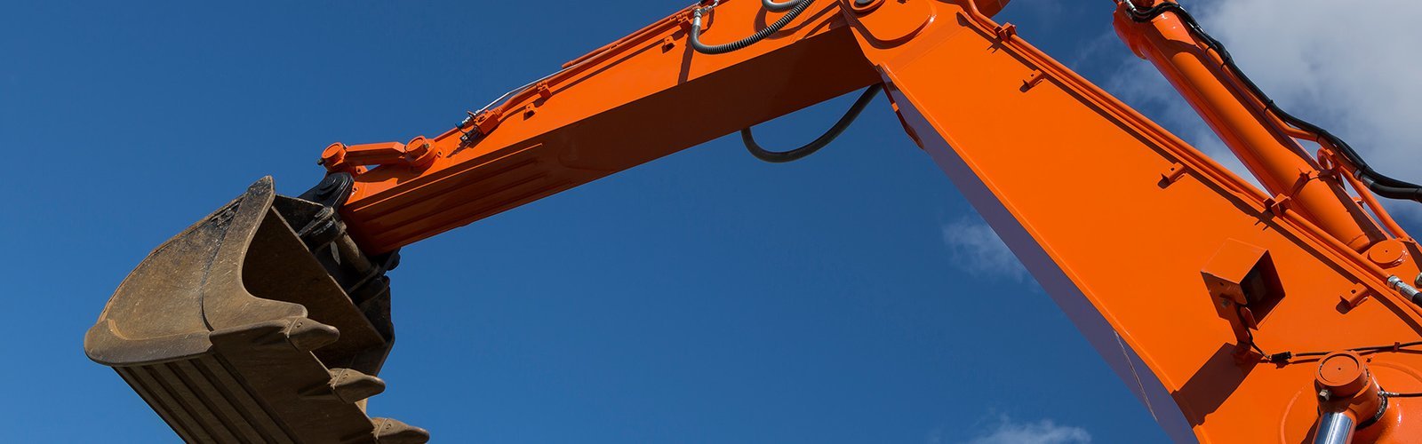
An excavator boom cylinder and a hydraulic press cylinder are both “heavy-duty”. That is where the similarity stops. One runs 35 MPa pressure spikes at 200 mm/s with mud packed against its wiper, four thousand hours a year. The other runs 28 MPa at 3 mm/s in a clean plant, sometimes for twenty years without a rebuild. Fit the press seal stack to the excavator and it will leak within a season. Fit the excavator stack to the press and you have paid for impact resistance the machine never uses.
This guide separates the two duties, then works through the excavator cylinder position by position: what each seal has to do, what it is usually made of, and the numbers that decide whether it survives. The press side gets its own section at the end, because buyers who source both from the same factory keep asking for one document.
Why the Two Duties Divorce the Design
Four variables separate a mobile cylinder from an industrial one: pressure profile, sliding speed, side load, and contamination. Take them one at a time.
Pressure profile. A press holds a set pressure for a long dwell and rarely overshoots. An excavator hits relief pressure every time the operator stalls the bucket, and the relief valve cracks and reseats several times a second while the machine works against a rock. That produces pressure ripple on top of the static load. A rod seal that sees 35 MPa static twice a day is a different component from one that sees 35 MPa plus 5 MPa of ripple, 400,000 times.
Sliding speed. Press rams move at 1–10 mm/s and spend most of their life stationary under load. Excavator rods move at 100–300 mm/s and reverse direction every few seconds. Slow motion builds no hydrodynamic film and lets the seal sit in one place, which is why press seals fail by compression set and extrusion; fast reciprocation builds a film, pumps oil back, and wears the lip by abrasion.
Side load. A press is guided by columns. An excavator cylinder is guided by its own guide rings and by the pin joints, and the bucket teeth put a bending moment straight into the rod. Guide ring wear is the first failure in most high-hour excavator cylinders, and it takes the rod seal with it.
Contamination. Press oil is filtered and enclosed. Excavator oil is filtered too, but the rod spends its life in quarry dust, and every retraction drags a film of abrasive slurry toward the gland. Field oil samples from 5,000-hour machines routinely read ISO 4406 19/17/14, against a 16/14/11 target.
Oil temperature and service life complete the picture. Excavator oil runs 50–85 °C, driven by ambient and by how hard the machine works; a press runs 35–55 °C under control. Life targets follow: 4,000–8,000 hours on a mobile machine, 15,000–30,000 on a press. Two designs can look identical on a drawing and be optimised for completely different cost-per-hour maths.
The Four Numbers That Decide the Stack
Before a single part number is quoted, four numbers settle most of the selection. Get them wrong and the seal material debate is pointless.
1. Bore, rod and stroke. Not nominal. Measured. A worn bore of 120.15 mm changes the piston seal squeeze, and a rod that has been re-chromed 0.05 mm oversize will not enter a standard wiper. We ask for the cylinder drawing plus a measurement of the old parts.
2. Relief valve setting, not working pressure. The seal sees what the relief lets through, plus the pressure spike when a hot circuit closes a spool. On a 20-tonne class machine the main relief is usually set at 32–35 MPa; the boom circuit may see 38 MPa on a stall. Order the seal for the relief setting, then add one margin step for the spike.
3. Cycle rate and stroke. A hammer circuit and a boom circuit use the same oil and different seals. High cycle counts favour PTFE-faced step seals on the rod; low cycle counts with high holding load favour loaded PU U-cups.
4. Oil type and temperature. Mineral ISO VG 46 is the default. Bio-oil (HETG, HEES) attacks some NBR compounds and many PU grades by hydrolysis. Fire-resistant water-glycol needs a different elastomer family entirely. If the machine runs in a foundry or a desert, ambient temperature moves the whole stack.
Position by Position: What Each Seal Is Actually Doing
An excavator cylinder kit contains six functional positions. Suppliers quote them as a set, and buyers often assume the set is interchangeable across brands. It is not: groove widths, radii and back-up arrangements differ, and the same 100 mm bore can take three different piston seal profiles.
| Position | Job | Usual material | Usual hardness | Typical failure |
|---|---|---|---|---|
| Rod seal | Hold pressure, return oil film, no external leak | PU U-cup, or PTFE step seal with NBR energizer | 93–95 Shore A (PU) | Lip wear from grit, then extrusion into the gland gap |
| Buffer seal | Absorb the pressure spike before it reaches the rod seal | PU or PTFE with a relief lip | 93–95 Shore A | Fatigue cracking at the relief lip; often missed at rebuild |
| Piston seal | Separate head and rod chambers, hold load without drift | PTFE step seal, or loaded PU ring | Shore A 95 / Shore D 55–60 for PTFE | Scoring from bore damage; loss of energizer squeeze |
| Wear / guide ring | Centre the piston, carry side load, stop metal contact | PTFE-bronze, phenolic, glass-filled nylon, PEEK | — | Wear to under-thickness, then piston-to-bore contact |
| Wiper | Scrape mud and dust off the entering rod | PU double lip, sometimes metal-cased | 93 Shore A | Lip torn or hardened; then the rod seal follows |
| Static O-rings | Seal gland, port and head joints | NBR 70, HNBR 90, FKM 80 for hot duty | 70–90 Shore A | Compression set, nibbling at the joint face |
We build these as matched kits — see our hydraulic seal kits and spare seals range — with the individual piston seal and rod seal profiles available separately when only one position has failed.
Two of these carry most of the warranty risk: the rod seal and the wiper. The piston seal gets the attention because internal bypass is easy to diagnose, but in our return analysis the rod seal plus wiper pair accounts for roughly two-thirds of external-leak claims.
Piston Seals: Step Seal or Loaded U-Cup
The piston seal has to do two contradictory things: seal at near-zero pressure so the load does not creep down, and survive 35 MPa without extruding into the bore clearance. Elastomer alone struggles with both. That is why most excavator pistons now use a two-piece design — a low-friction plastic face ring for the pressure seal and an elastomer energizer for the static tightness.
| Design | Pressure ceiling (practical) | Breakaway friction | Groove width | Where it belongs |
|---|---|---|---|---|
| PTFE step seal + NBR O-ring energizer | 35–40 MPa with back-up | Low, stable after run-in | Wide, ISO 7425-1 style | Boom, arm and bucket pistons on 13–40 t machines |
| Loaded PU U-cup (single piece) | 25 MPa | Higher, rises as PU hardens | Narrow | Small-bore and auxiliary cylinders, older groove geometries |
| PU compact seal with integrated guide | 25–31.5 MPa | Moderate | Narrow | Retrofit where the piston groove cannot be widened |
| Two-piece PU + PTFE back-up | 31.5 MPa | Moderate | Medium | Budget rebuild of a step-seal piston |
The step seal wins on friction and on holding, but it needs a wider groove and a good bore finish. Honing to Ra 0.2–0.4 µm matters more than most rebuilders expect: a torn bore finish acts as a lap and wears the PTFE face in a few hundred hours.
Rod Seals and Buffer Seals: the Pair, Not the Part
The rod seal is the only component between pressurised oil and the outside world, and it is also the component that has to let a microscopic oil film pass to lubricate the wiper. That balance is the whole design.
On an excavator, a single U-cup rod seal is common up to about 25 MPa. Above that, and on any circuit with fast cycle rates, the buffer seal earns its groove. The buffer sits outboard of the main rod seal, takes the pressure spike on its own lip, and vents the trapped oil back to the tank through a small relief passage. The rod seal behind it then only sees the residual pressure, which extends its life several-fold on hammer and breaker circuits.
Rebuilders skip the buffer more often than any other part, usually because it is a thin ring that looks like a spacer. Then the new rod seal fails in 300 hours and the kit gets blamed.
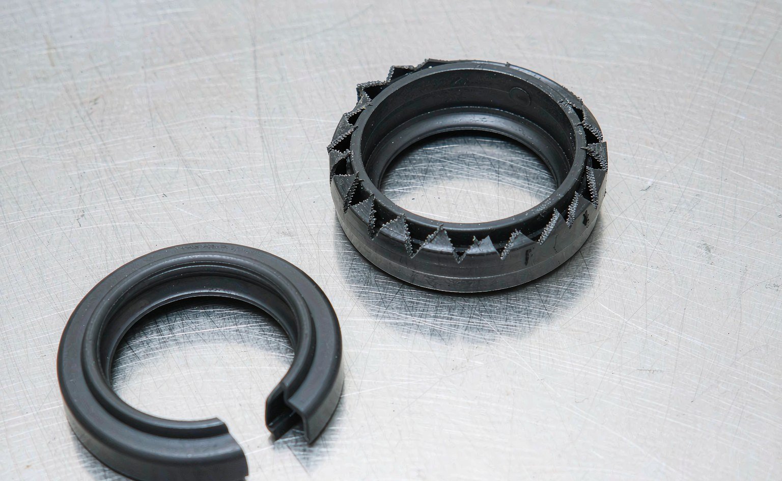
If the old rod seal shows a clean circumferential cut at the lip heel, the buffer was missing or already destroyed. If it shows a chewed, grit-filled lip, the wiper failed first. The wear pattern tells you which part to change in the design, not just in the kit.
Wiper Selection: Where Mud Decides the Service Interval
A wiper has one job and a hostile workplace. It must remove abrasive film from a chrome rod moving at 200 mm/s without lifting oil off the rod on the return stroke, and it must do that while packed with the same abrasive it is removing.
Three configurations cover most machines. A single-lip PU wiper seal is adequate for clean sites. A double-lip PU wiper with a metal case adds a second scraping edge and holds its shape in a hot gland. A PU wiper with an integrated dust lip and a separate metal backing ring is the choice for demolition and quarry work, where the rod comes back coated rather than damp.
Clearance matters as much as compound. If the wiper sits in a gland where the rod-to-bore clearance allows the lip to be pushed outward by packed dirt, it will invert. We have seen inverted wipers on machines that never left a paved yard — the cause was a gland machined 0.3 mm oversize, not the material.
Guide Rings and Side Load: the Alignment Problem
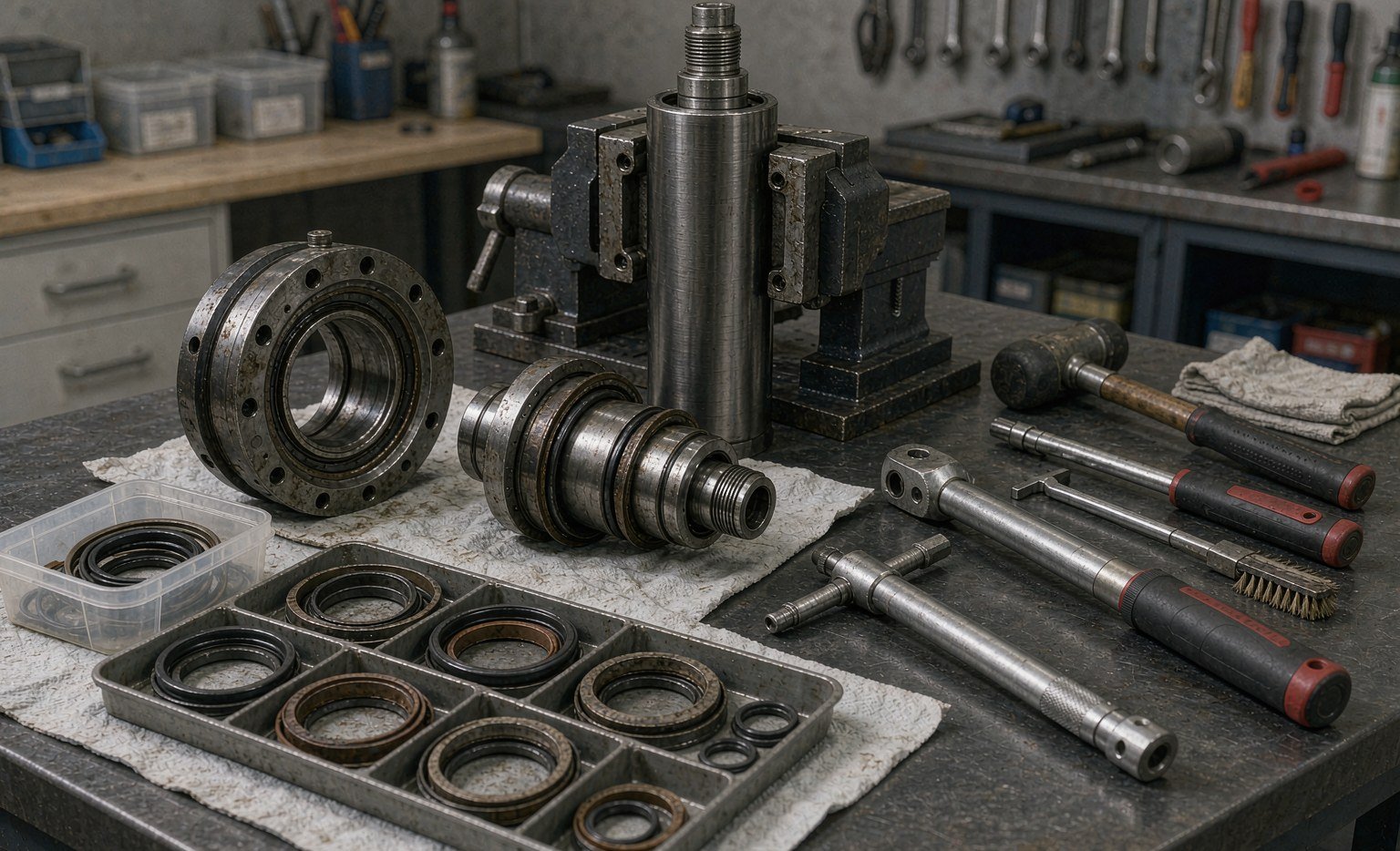
Guide rings — wear rings, bearing strips, guide bands — do not seal anything. They hold the piston and rod concentric so the seals can do their job at the clearance they were designed for. When they wear, the piston drops onto the bore, the seal gap opens on one side, and extrusion starts.
| Guide material | Load capacity | Wear behaviour | Temperature ceiling | Best use |
|---|---|---|---|---|
| PTFE-bronze | High | Low friction, some embedment of grit | About 200 °C | Rod guides and piston wear rings on high-cycle cylinders |
| Phenolic fabric | Very high | Good in dirty oil, can swell in water-based fluid | About 120 °C | Heavy pistons, press cylinders, high side load |
| Glass-filled nylon | Medium | Abrasive to the counterface when dry | About 100 °C | Cost-driven OEM pistons |
| PEEK (virgin or carbon-filled) | High | Very low wear, dimensional stability | About 250 °C | Hot, high-load, or thin-section guides |
Guide ring thickness is set by the clearance it must close, not by the seal groove. A worn guide of 1.5 mm nominal that measures 1.1 mm has already doubled the diametral clearance; the piston seal behind it is now extruding into a gap it was never rated for. That is the mechanism behind most “the new seals failed in a month” complaints.
Pressure, Gap and Extrusion: Sizing the Back-Up
Extrusion resistance is a clearance problem before it is a material problem. Every pressure seal has a maximum diametral gap at a given pressure and temperature; exceed it and the seal cold-flows into the gap, starting at the hottest point of the cycle.
The practical rules we work to on mobile cylinders:
- Up to 16 MPa, a 90 Shore A PU seal can usually run without a back-up at standard clearances.
- 16–25 MPa, add a single back-up on the low-pressure side or specify a seal with an integrated anti-extrusion heel.
- 25–40 MPa, use a back-up on both sides of the O-ring, or a plastic-faced seal in a closed groove, and keep the gap under the value in the supplier’s table for that temperature.
- Above 40 MPa, treat the joint as a high-pressure design: closed groove, hard back-up (PEEK or filled PTFE rather than soft PTFE), and a bore that will not deflect under load.
Temperature moves all of those numbers. A PU seal rated to 40 MPa at 40 °C loses roughly half its extrusion margin at 80 °C, because the material softens and the clearance opens as the cylinder barrel expands. Machines that work in summer heat with black-painted barrels see exactly this.
For the actual limits, work from a published clearance table rather than a rule of thumb: Trelleborg’s sealing solutions library and the Hallite fluid power catalogue both tabulate maximum gap against pressure, hardness and temperature, and both use the ISO 5597 housing dimensions that most excavator glands follow.
Fluid and Temperature: the Silent Variable
Mineral oil at 50–80 °C is the easy case, and most excavator kits are built for it. Three other fluids appear often enough to plan for.
Bio-oil (HETG, HEES). Ester-based fluids hydrolyse polyester PU and swell some NBR compounds. A polyester PU rod seal in a bio-oil machine can lose hardness and take a permanent set within a season. This is one of the few cases where we recommend a polyether PU or an HNBR compound instead of the standard part. General fluid charts such as Marc Rubber’s O-ring material selection guide are a reasonable first screen, but they rate base polymers, not compounds, so confirm the specific grade with the supplier.
Water-glycol (HFC). Poor lubricity, and it attacks many PU grades. HNBR or NBR with a PTFE-faced rod seal is the usual answer.
Hot ambient. A machine working in a steel mill or a desert sees oil at 90–100 °C. Standard PU is at its limit; HNBR for the static seals and a PTFE step seal on the rod hold up better than any PU upgrade.
None of these changes are expensive at the quoting stage. All of them are expensive after a failure, because the kit has to be rebuilt and the machine is down.
The Press Cylinder: Same Hardware, Different Priorities
Press cylinders run slow, hot and clean. That inverts most of the excavator logic.
Slow motion means no hydrodynamic film. The seal runs boundary-lubricated, and the lip must be able to hold pressure while nearly stationary. Compression set becomes the dominant failure mode, not abrasion. A compound with a low compression set at 80 °C — measured per ASTM D395 Method B, 22 h at 100 °C for a comparable rating — matters more than tensile strength.
Steady pressure means the back-up is doing continuous work rather than surviving spikes. On a 31.5 MPa press, a PTFE back-up that cold-flows will creep out of the groove over months. Filled PTFE or PEEK, in a closed groove, is the durable choice.
Clean oil means the wiper is a formality and the guide rings can be thinner. It also means the bore finish is usually excellent, which lets a PTFE-faced seal run at very low friction — useful on a press with a slow approach stroke where stick-slip shows up as a mark on the workpiece.
Two configurations cover most presses: a fabric-reinforced V-packing set for the main ram, adjusted by a gland nut, and a compact PTFE step seal plus guide ring for the return and ejector cylinders. The V-packing tolerates wear by taking up adjustment; the step seal does not, but has far lower friction.
Cross-Referencing an OEM Kit Without Getting Burned
Machine owners rarely have a seal drawing. They have a part number from the parts book, or a bag of old seals. Both routes work, with caveats.
Part-number cross-reference is fast but shallow: one OEM number can cover three different cylinder builds across a model’s production run. Aftermarket listings of the kind this distributor publishes are useful for establishing what a kit should contain, and catalogues such as PPE help when a US-sourced equivalent has to be checked against an OEM number. Neither tells you the groove width. We always ask for the cylinder casting or assembly number as well, and we compare the old seal dimensions against the drawing before quoting.
Measuring the old parts is more reliable, provided the parts are not destroyed. Measure the rod seal in its free state and note the lip profile; measure the piston seal width across the back, not at the lip; measure guide ring thickness at four points because wear is rarely even. Photograph the gland with a scale in frame. Nine out of ten cross-reference errors we see come from a measurement taken on a swollen or worn part rather than a clean one.
Installation Faults That Mimic Material Failure
Four faults account for most of the “wrong material” claims we investigate:
- Diagonal cut or shaved lip on one side. The seal was dragged over a thread, keyway or sharp gland edge. Tape the threads, chamfer the gland lead-in, and coat the seal in the system oil before fitting.
- Seal twisted in the groove, leak at one point. Installed dry, or rolled rather than folded into the groove. Use a fitting cone and check seating with a feeler before the gland goes on.
- Hard, cracked lip after 200 hours. Wrong fluid or a contaminated flush, not a compound fault. Sample the oil and look for solvent or water ingress before changing the specification.
- Guide ring worn through on one side only. A bent rod or a worn pin bore is putting a permanent side load on the gland. Check rod straightness and pin bore diameter before fitting the new kit.
Each of these costs a kit and a day of machine downtime. None of them is fixed by buying a more expensive compound.
What We Ask for on an Excavator RFQ
Our own RFQ form for mobile cylinder kits has eight lines, and a complete submission gets a quote in a day rather than a week:
- Machine make, model and serial range.
- Cylinder position — boom, arm, bucket, swing, travel, hammer, thumb.
- Cylinder assembly or part number, plus bore × rod × stroke if known.
- Relief pressure and whether the circuit has a buffer seal groove.
- Oil type and normal operating temperature.
- Site conditions — quarry, demolition, tunnelling, port, agriculture.
- Quantity per year and whether the order is one-off or scheduled.
- Any packaging or marking requirement for resale.
For distributors, the eighth line matters more than they expect. A kit packed as a loose bag of rings sells badly at a counter; the same kit on a printed card with the machine model and a position diagram sells at a premium. That is a packaging decision, not a sealing one, but it is part of what a factory should be able to do for you.
Key Takeaways
- Excavator and press cylinders share hardware, not duty. Pressure ripple, rod speed, side load and dirt drive the design in opposite directions.
- Specify against relief pressure plus one margin step, not against nominal working pressure.
- The buffer seal is not optional above roughly 25 MPa on high-cycle circuits; skipping it is the most common rebuild error we see.
- Guide ring wear opens the extrusion gap long before the seal itself fails. Check guide thickness at every rebuild.
- PU at 93–95 Shore A covers most mobile cylinders; bio-oil, water-glycol and hot ambient each require a specific change of compound.
- Most “material failures” are installation damage or contaminated oil. Diagnose the wear pattern before changing the specification.
- A complete RFQ — machine, position, dimensions, relief, fluid, site — is worth more than a photo of the old seal.
If you are rebuilding a fleet and want the stack reviewed position by position, send the cylinder drawing and the relief setting. We will come back with a proposed bill of materials, the groove dimensions it needs, and the two or three places where the original design is likely to fail again.
Related reading on this site: what a hydraulic cylinder seal kit contains and how to order one, the ten causes of hydraulic seal failure we see most often, and rod seals versus piston seals.
The Whole Stack, From One Drawing Set
A cylinder stack is a system, and we quote it that way: piston seals in step-seal or loaded U-cup form, rod and buffer seals, wipers, guide rings, back-up rings and the O-rings underneath them — in PU, PTFE compounds, NBR, HNBR and PEEK. Sizes can follow an OEM kit or be built to the groove dimensions you measure.
Where a kit is being cross-referenced we check four numbers before anything is priced: bore, rod, groove width and the pressure-gap pair. An excavator kit that fits the bore but not the groove is the most expensive kind of correct. Mud-side duty earns a wiper recommendation; high side load earns a guide-ring wall thickness, not a thicker seal.
Send the cylinder drawing, the OEM part numbers or a photo of the failed stack with the machine’s duty, and we will return a proposed bill of materials, the groove dimensions it needs and the points where the original design is likely to repeat. Price and lead time follow within a day, engineering review free — sales@bosssealing.com or the contact form.