
A drawing that says “O-ring, NBR 70, for 1.000 in bore” is not a specification. A drawing that says AS568-214, NBR 70 is. The dash number carries the inside diameter and the cross-section in one three-digit code, and it does the same thing on a hydraulic print in Ohio, a pump rebuild kit in Hamburg, and a packing list in a Bangkok warehouse. That is the entire value of the SAE AS568 system: one geometry language that survives translation between OEMs, distributors and repair shops.
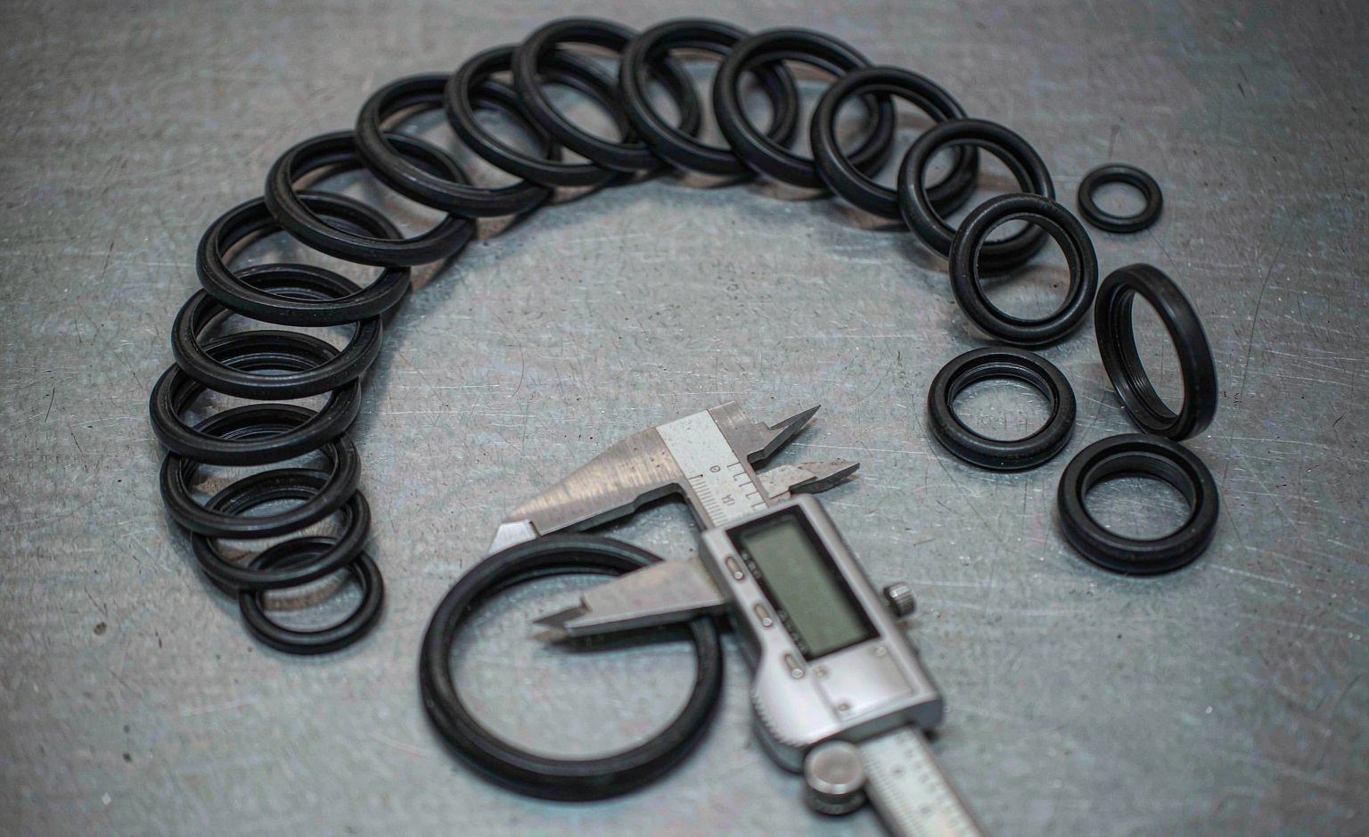
We manufacture and machine O-rings and sealing components for hydraulic, pneumatic and rotary applications, and the questions that come in from buyers are rarely about the rubber. They are about the numbers: what does -214 actually mean, what tolerance comes with it, and what happens to squeeze if the groove was machined for a different cross-section. This article answers those questions with the actual table values, not approximations.
The Five Cross-Section Series
AS568 organizes its sizes into families by cross-section (CS). The first digit of the dash number tells you the family, and the family fixes the cross-section within a narrow tolerance. Five general-purpose series cover most fluid-power work, plus three small special sizes below the 1.78 mm cord and a separate 900-series reserved for SAE straight-thread tube-fitting boss gaskets (ORB ports).
| Series | Dash range | Nominal CS (in) | Nominal CS (mm) | CS tolerance | Typical duty |
|---|---|---|---|---|---|
| 000 | -004 to -050 | 0.070 | 1.78 | ±0.003 in | Small fittings, instrumentation, pneumatics |
| 100 | -102 to -178 | 0.103 | 2.62 | ±0.003 in | ORB ports, small cylinders and valves |
| 200 | -201 to -284 | 0.139 | 3.53 | ±0.004 in | General-purpose cylinders, pumps |
| 300 | -309 to -395 | 0.210 | 5.33 | ±0.005 in | Heavy hydraulic, large flanges |
| 400 | -425 to -475 | 0.275 | 6.99 | ±0.006 in | Large-bore cylinders, static flange joints |
Three sizes sit below the standard cord: -001, -002 and -003, with cross-sections of 0.040, 0.050 and 0.060 in (1.02, 1.27 and 1.52 mm). They have no metric counterpart in ISO 3601-1 and mostly serve instrumentation. The 900 series (-901 to -932) is a different animal entirely: mixed cross-sections, sized for SAE J1926 straight-thread boss ports, and worth treating as its own catalogue when you stock for hydraulic fittings.
Counting every dash number from -001 through -475, AS568 lists roughly 349 general-purpose sizes plus the 20 boss sizes — around 369 geometries in total. In practice, distributors keep the 100 and 200 series complete because those two families cover the majority of cylinder, valve and pump glands, and stock the 300 and 400 series on the shelf for large static joints. Our standard O-ring and X-ring range follows the same logic, with the light 000 series held for pneumatic and instrument work.
Where the Standard Came From — and Why the Letter Matters Less Than You Think
SAE International’s A-6C2 Seals Committee issued the original AS568 in July 1971 to end a real logistics problem: before the standard, US aerospace and military OEMs specified proprietary O-ring dimensions, so spares did not interchange, tooling multiplied, and field repair turned into a drawing hunt. The US Department of Defense later adopted SAE-AS568 for packing and gasket use, which locked the dash system into military and industrial procurement — and into the legacy military part numbers you will still meet. MS28775 packing callouts, for example, map dash-for-dash onto AS568 sizes, which is why a NOK or Parker catalog quote for an MS-sized gland reads the same geometry as an AS568-210.
The document has moved through revisions — AS568A, AS568B (2001), AS568C (2008, added metric equivalents), AS568D (2014), AS568E (2020, technical corrections), and AS568F, the current letter. In everyday buying nobody says “AS568F”: people say AS568, AS568A or just “the dash number,” and every revision since 1971 has kept the dash-number geometry itself stable. A -214 ordered to AS568B in 2005 and a -214 ordered to AS568F today describe the same ring. That backward compatibility is worth knowing when you service equipment old enough to vote.
One warning attaches to the history: AS568 defines geometry only. The material specifications that ride alongside it on aerospace drawings (AMS compound callouts, military packing specifications) are separate documents with their own approval trails. A supplier who offers “AS568” rings without stating which material spec or certificate accompanies them is selling size without substance.
How to Read a Dash Number on a Drawing
The dash number is an index into a fixed table, not a formula. The first digit selects the cross-section family; the remaining digits step through inside diameters within that family, rising in roughly 1/16 inch (1.59 mm) increments per step in the 100 through 300 series. Because the mapping is a table lookup, two dash numbers that “look” numerically close can sit in different series with different cross-sections — -114 and -214 are nowhere near interchangeable.
Outside diameter is a reference dimension, not a controlled one: OD = ID + 2 × CS. Inspection departments check ID and CS and leave the OD alone, because the tolerances on ID dominate how the ring behaves in the gland.
The table below lists the dash numbers that show up most often in hydraulic and general-industrial maintenance work, with both unit systems. If you stock seal kits, most of your moving parts are in the middle twelve rows.
| Dash No. | CS (in / mm) | ID (in) | ID (mm) | OD (in) | Where it turns up |
|---|---|---|---|---|---|
| -006 | 0.070 / 1.78 | 0.114 | 2.90 | 0.254 | Instrumentation ports |
| -010 | 0.070 / 1.78 | 0.239 | 6.07 | 0.379 | Small threaded fittings |
| -110 | 0.103 / 2.62 | 0.362 | 9.19 | 0.568 | SAE ORB fittings |
| -116 | 0.103 / 2.62 | 0.676 | 17.17 | 0.882 | Medium fittings, small valves |
| -210 | 0.139 / 3.53 | 0.739 | 18.77 | 1.017 | Valve glands |
| -214 | 0.139 / 3.53 | 0.984 | 24.99 | 1.262 | Common cylinder and pump gland |
| -219 | 0.139 / 3.53 | 1.296 | 32.92 | 1.574 | Rod and piston glands |
| -325 | 0.210 / 5.33 | 1.859 | 47.22 | 2.279 | Large flanges |
| -335 | 0.210 / 5.33 | 2.688 | 68.27 | 3.108 | Heavy-duty static joints |
| -437 | 0.275 / 6.99 | 5.350 | 135.89 | 5.900 | Large-bore cylinders |
One note on field identification: if a ring arrives unmarked, measure ID and CS with a caliper, then match both numbers against the chart. Never match on OD alone — a -214 and a metric 25 × 3.5 ring are nearly identical on OD but differ enough on CS to change squeeze and gland fill. Our earlier article on how to measure an O-ring correctly covers the caliper technique and the common measurement traps.
What AS568 Controls — and What It Leaves to the Material Spec
AS568 is a size standard. It fixes ID, CS, tolerances and the dash-number code. It says nothing about compound, durometer, color or certification. Those ride on the purchase order as a separate material callout: an AMS specification for aerospace, an FDA-reviewed compound for food contact, or a plain “NBR 70 Shore A” for industrial work. When a customer sends us an RFQ that says only “AS568-214 Viton,” the first thing our quotation does is pin down the actual compound requirements, because “-214” alone guarantees geometry and nothing else.
On tolerances, the cross-section limits are tight and uniform: the 0.070 in and 0.103 in series carry ±0.003 in (±0.08 mm), rising to ±0.006 in (±0.15 mm) for the 6.99 mm cord. Inside-diameter tolerance scales with size. In metric terms, using ISO 3601-1 Class B bands that track the AS568 values closely, a -020 (21.95 mm ID) carries ±0.28 mm, a -035 (56.87 mm ID) carries ±0.55 mm, and a -050 (133.07 mm ID) carries ±1.0 mm. Aerospace callouts tighten this further with their own AMS-P material and inspection requirements — suppliers serving that market run Class A or tighter and say so explicitly on the dimensional report.
For buyers comparing quotations, the practical question is not whether a supplier “meets AS568” (any competent moulding shop does) but which tolerance class the certificate references and whether it is measured per lot or per moulding cavity. We measure per lot on production rings and per cavity on new tooling sign-off; that is the level of detail that separates a repeatable supplier from a cheap one. The ISO 3601 size system parallels AS568 with its own Class A and B tolerance definitions, and mixing the two in one gland is a design error we will come back to below.
From Dash Number to Groove: Squeeze, Fill and Stretch
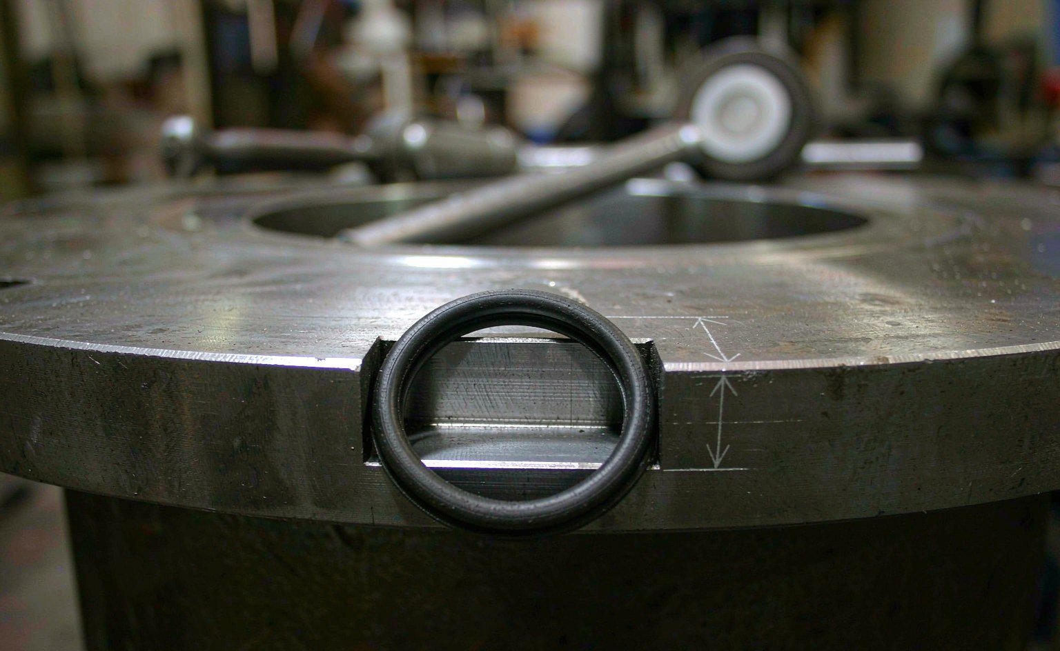
The dash number only tells you what ring you bought. Whether it seals depends on three ratios between the ring and the gland:
- Squeeze = (CS − gland depth) ÷ CS. Static face glands run 20–30%; static radial glands run 15–25%; sliding (dynamic) glands run 8–16%, with low-friction pneumatic applications at the bottom of that band.
- Stretch = (groove ID − ring ID) ÷ ring ID. Keep it below about 5%. More stretch than that thins the cross-section, drags the ID tolerance into the calculation, and promotes spiral failure in dynamic service.
- Gland fill = ring cross-sectional area ÷ groove cross-sectional area. Target 60–85%, and bias toward the low end whenever the compound can swell in the system fluid.
Groove width should land near 1.3–1.5 × CS so the deformed ring has somewhere to go. The values below reflect ISO 3601-2 style gland dimensions, which are consistent with the gland tables most AS568 hardware is actually machined to. Note how squeeze percentage falls as cross-section grows — a 6.99 mm ring at 14–17% squeeze delivers a larger absolute squeeze distance than a 1.78 mm ring at 25%, which is why big static joints tolerate looser machining.
| CS (mm) | Static gland depth (mm) | Static squeeze | Dynamic gland depth (mm) | Dynamic squeeze | Groove width (mm) |
|---|---|---|---|---|---|
| 1.78 | 1.30 – 1.35 | 24 – 27% | 1.47 – 1.50 | 16 – 17% | 2.4 – 2.5 |
| 2.62 | 2.00 – 2.05 | 22 – 24% | 2.20 – 2.22 | 15 – 16% | 3.4 – 3.6 |
| 3.53 | 2.70 – 2.82 | 20 – 24% | 2.95 | 16% | 4.6 – 4.7 |
| 5.33 | 4.20 – 4.34 | 19 – 21% | 4.50 – 4.60 | 14 – 16% | 6.9 – 7.0 |
| 6.99 | 5.74 – 5.80 | 17 – 18% | 5.90 – 6.00 | 14 – 15% | 9.0 – 9.1 |
Surface finish completes the gland. Static sealing faces want Ra ≤ 1.6 µm; dynamic sliding surfaces need Ra 0.2–0.4 µm, ground or polished, or the ring will abrade and leak within weeks. The groove surface finish article covers the failure signatures in detail. Break every groove edge R0.2–0.5 and chamfer lead-ins 15–20° — a sharp port edge is the most common cause of nicks found at incoming inspection.
A Worked Example: Building the Gland for a -214
Numbers make the ratios concrete, so take the most common general-purpose size, the -214 (0.984 in / 24.99 mm ID, 0.139 in / 3.53 mm CS), and design a static radial gland around it.
Squeeze. Pick a static radial depth of 2.75 mm. Squeeze = (3.53 − 2.75) ÷ 3.53 = 22.1% — inside the 15–25% band for radial static service. If the same gland were a reciprocating rod seal, the depth would open to about 2.95 mm, giving 16.4%, which trades leakage margin for friction and heat.
Gland width and fill. Groove width at 1.33×CS is 4.7 mm. Ring cross-sectional area = π/4 × 3.53² = 9.79 mm². Groove cross-sectional area (approximating the cavity as width × depth, which is how most shops sanity-check it before running the CAD model) = 4.7 × 2.75 = 12.9 mm². Fill = 9.79 ÷ 12.9 = 76% — comfortably inside the 60–85% target and with enough headroom for a modest thermal expansion of the compound. If the system fluid swells the compound more than a few percent, drop the width to the upper end of the band or re-check fill against the swelled cross-section.
Stretch. The ring’s ID is 24.99 mm. For a piston-mounted ring (ring stretched over the piston groove), a groove diameter of 25.75 mm gives stretch = (25.75 − 24.99) ÷ 24.99 = 3.0% — legal, but note that stretch thins the cross-section by roughly 1.5% and that the squeeze calculation should use the installed cross-section, not the free one, when stretch approaches the 5% limit.
Extrusion. At what pressure does this gland need a back-up ring? That depends on the diametral clearance and the compound hardness — a 90 Shore A NBR with a tight 0.1 mm gap runs far past what a 70 Shore A compound tolerates in a 0.3 mm gap. The full logic lives in our article on why hydraulic seals leak at high pressure, but the design habit is simple: decide the back-up question at gland-design time, not after the first teardown.
Run the same four numbers — squeeze, fill, stretch, extrusion gap — against any dash number and any gland, and the drawing conversation with a supplier becomes a five-minute exchange instead of a week of email. Suppliers’ engineering teams can check a candidate gland against their compound data in one pass when all four numbers arrive together.
Hardness and Compound: The Other Half of the Callout
Because AS568 stops at geometry, the compound decision arrives separately — and it changes how the same ring behaves in the same gland. The working distinctions:
- 70 Shore A vs 90 Shore A. The harder compound resists extrusion better and needs less squeeze to seal gas; the softer compound conforms better to imperfect surfaces and seals at lower contact loads. Most industrial hydraulics run 70 Shore A with back-up rings taking the extrusion duty; aerospace glands often run 90 Shore A compounds specified by AMS callout.
- Compound family sets the temperature and chemical envelope. The same -214 in NBR serves −40 to +100 °C in oil-based media; in FKM it survives +200 °C and aggressive chemistry; in EPDM it handles steam and glycol but dies in petroleum oil. Geometry is constant; the medium decides the family.
- Compression set behavior scales with hardness and compound, not size. A 70 A NBR -214 and a 90 A FKM -214 in identical static glands age differently: the FKM holds its shape at temperature, the NBR takes a set and relaxes. Long-dwell static applications (valve stems, test equipment, safety-circuit accumulators) should select on compression-set data, not price.
When you send an RFQ, name all three: dash number, compound family, hardness. “AS568-214, FKM 75” is a complete geometric and material start point; a quotation can come back the same day. “AS568-214 O-rings” starts a conversation — usually the same three questions, every time.
Three Mistakes That Show Up at Incoming Inspection
1. Swapping a metric ring into an inch gland (or the reverse). A 25 × 3.53 ring looks like a -214 and differs by fractions of a millimetre — exactly enough to push squeeze below the leakage threshold or fill above the swell limit. The fix is administrative, not technical: print the dash number (or the ISO code) on the drawing and refuse substitutions without a gland recheck. We keep a conversion note in every quotation that involves a cross-standard substitution, and we ask for the gland drawing before we approve one.
2. Stretching to fit. Maintenance crews install a ring one size small because it is in the drawer. Past about 5% stretch the cross-section thins, the effective squeeze drops, and in reciprocating service the ring starts to spiral. If the correct dash number is unavailable, an adjustable approach — a back-up ring and the correct ring, or a kit — beats a stretched substitute every time. Suppliers with meaningful stock depth exist precisely because this mistake is expensive; general references such as Seal Sales and ERIKS publish the full dash-number charts openly, so “we could not find the size” is a stocking problem, not an information problem.
3. Treating the OD as the controlled dimension. OD is ID + 2×CS, a reference value. Buyers who qualify suppliers on OD match alone let CS drift, and CS is what sets squeeze. Inspect ID and CS; let the OD land where it lands.
AS568, ISO 3601 and JIS B 2401 on One Purchase Order
Global equipment mixes all three systems. AS568 dominates North American and aerospace hardware; ISO 3601 carries the metric sizes in European and increasingly global machinery; JIS B 2401 defines the Japanese P, G and S series with their own cross-sections. There is no direct code-to-code conversion — a “close” JIS ring to a -214 may differ on ID by enough to matter in a 25 mm bore.
Three rules keep multi-standard hardware sane. First, convert by measured geometry (ID and CS in mm), then verify the gland against the chosen standard — the ISO 3601 tolerance-class differences make a code-to-code conversion impossible. Second, name the standard on the PO line, not just the dimensions, so the certificate matches the callout. Third, when the hardware is American and the drawing is ambiguous, default to AS568 and say so in the RFQ — that single word shortens the quotation cycle, because the moulding plan, tooling check and tolerance class all follow from it. Industry reference catalogs such as Precision Polymer Engineering and seal manufacturers like Trelleborg, whose gland-design handbooks reproduce the AS568 tables alongside squeeze guidance, follow the same table — which is the point of a standard: the dash number means the same thing everywhere. Cross-checking a supplier’s chart against a manufacturer handbook takes ten minutes and catches transcription errors before they reach a groove.
Stocking Strategy: Which Dash Numbers a Distributor Actually Needs
For distributors and seal-kit builders, the full 369-size table is a mirage — demand concentrates hard. Based on what moves through our factory shipments and what trade customers reorder, a practical stocking plan looks like this:
- Complete 100 and 200 series (-102 to -178, -201 to -284) in two compounds: NBR 70 and FKM 75. These two families cover the majority of cylinder, valve, pump and ORB-fitting glands worldwide, and kit-builders pull from them constantly.
- The 000 series in NBR 70 and EPDM 70 for pneumatic and water-based service — the -006 through -025 range alone answers most instrument and fitting requests.
- Selected 300 and 400 series in FKM and NBR for large static joints: -309 to -395 in the sizes your local industry actually runs (food equipment tends toward the smaller 3xx sizes; mining and marine toward the larger ones and the 4xx series).
- The 900-series boss seals in NBR 70 and FKM 90 if you serve hydraulic fitting and manifold customers — 20 sizes, high turnover, almost no competition from metric-only suppliers.
- One low-temperature and one food-grade line in the fastest movers (-009, -010, -012, -110 to -116, -210 to -219): low-temperature NBR or HNBR for outdoor equipment, and an FDA-reviewed compound for the food, pharma and drinking-water callers.
The arithmetic that makes this work: a full two-family, two-compound 100+200 series holding is roughly 160 line items — a shelf wall, not a warehouse. Every dash number on that wall substitutes into dozens of different machines, which is the quiet advantage of a size standard: inventory flattens demand in a way proprietary sizes never do. The corollary is that price pressure concentrates too, because every distributor stocks the same -214 NBR ring. Where distributors escape the price trap is compound availability, tolerance certification and small-batch responsiveness — the non-geometric half of the callout, which is also the half AS568 does not standardize.
When a customer’s requirement falls off the wall — an odd compound, a tight tolerance class, a non-standard size derived from AS568 geometry — that is the custom-manufacturing conversation, and it is where the quotation moves from shelf price to specification review. The dash number still anchors it: tooling and inspection plans all start from the nearest AS568 geometry.
Key Takeaways
- AS568 has five general-purpose cross-section series (0.070 / 0.103 / 0.139 / 0.210 / 0.275 in), roughly 349 sizes, plus a 20-size 900-series for ORB boss ports.
- The dash number is a table index, not a formula; ID is the controlled dimension and OD is reference only (OD = ID + 2×CS).
- CS tolerances run ±0.003 in on the two smallest cords up to ±0.006 in on 0.275 in; ID tolerance widens with size (e.g., ±0.28 mm at 21.95 mm ID).
- AS568 fixes geometry only — compound, hardness and certification ride on the material callout.
- Design the gland to the ring: squeeze 15–25% static radial (20–30% face, 8–16% dynamic), stretch below 5%, fill 60–85%, width about 1.3–1.5×CS.
- Never substitute a metric ring for a dash number without re-checking squeeze and fill against the actual gland dimensions.
Dash Numbers, Compounds and Grooves on One Order
AS568 dash numbers are the working language of our O-ring supply: the full cross-section series in NBR, FKM, EPDM, silicone, HNBR and FFKM, in standard and non-standard compounds, with size, tolerance class and quality grade stated on the order. Metric and JIS sizes are handled the same way, and the drawing carries the standard rather than a note saying “equivalent”.
Where we add value is at the gland. If a dash number is being substituted, we check squeeze, stretch and fill against the groove before the parts ship, and we say when the nearest dash size is not the nearest fit. Hardness and compound are quoted as separate callouts because they move compression set and extrusion behaviour far more than the cross-section tolerance does.
Send the dash numbers or the groove drawing with the compound and duty, and you will get a quotation with size, class, grade and lead time spelled out — usually within 24 hours. Write to sales@bosssealing.com or use the contact form; the engineering review is at no cost.