
A guide ring does not seal anything, and that is exactly why it decides how long the seals around it last. When a piston or rod runs off-centre, the primary seal is forced to close a gap that is wider on one side than the other, and it extrudes, nibbles or wears on a single arc until it leaks. The guide ring — also called a wear band, wear ring, guide strip or bearing ring — takes that side load before it reaches the seal. Get it wrong and no seal compound will save the cylinder. Get it right and a standard NBR or PU seal will run for years on a bore it never touches.
This article covers the selection logic we use when customers send us a cylinder drawing: how to estimate the side load, how the three main material families compare, what the groove dimensions have to be, and which failure signatures point to the guide rather than the seal. Most of the field failures we analyse in this category are not material failures at all. They are thickness, gap or surface problems that a drawing check would have caught.
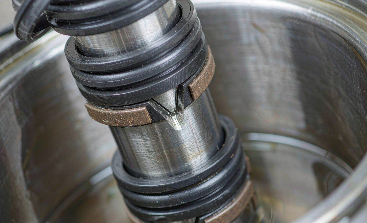
What a Guide Ring Does That a Seal Cannot
A hydraulic or pneumatic cylinder has two separate jobs at the same sliding interface. One is to hold pressure, which is the seal’s job. The other is to keep the moving part concentric with the bore, which is the guide’s job. Metal-to-metal guidance — a bronze bushing running directly on a chrome rod, or a piston skirt running on a honed tube — works, and older cylinder designs used it for decades. It also converts every side load into adhesive wear on two expensive parts, and it transfers vibration straight into the seal groove.
A polymer guide ring replaces that metal-on-metal pair with metal-on-polymer. Four things follow from that substitution:
Radial load path. Side load from a rod that is not perfectly aligned, from a linkage pushing at an angle, or from the weight of a horizontal piston and rod, is carried by the guide ring into the bore wall over a defined contact area. The seal never sees it.
Concentricity. Two guide bands spaced apart on the piston, or one band on the piston plus one in the gland, hold the axis. A single narrow band allows the piston to cock; a cocked piston pinches the seal on one side and opens a gap on the other.
Lower friction and no stick-slip. Filled PTFE runs at a dynamic coefficient of friction roughly in the 0.05–0.15 range against steel, and its static and dynamic values are close. That closeness is what removes the jerky low-speed motion that a dry elastomer seal produces.
Contamination tolerance. A polymer band is softer than the bore and can embed small particles instead of dragging them across the sealing surface. It also acts as a secondary wiper in dirty service.
The practical consequence: a cylinder with a worn guide ring leaks even when the seal is intact, because the seal is being asked to do a geometry job. Mechanics who replace the seal and skip the guide usually see the same leak back within weeks.
Start With the Side Load, Not the Material
Material choice is the second question. The first is how much radial force the guide has to carry, because that number sets the contact pressure, and contact pressure sets both the material and the band width.
The bearing pressure calculation is short:
p = F / (d × L)
where p is the specific load in N/mm², F is the radial force in N, d is the sliding diameter in mm and L is the total axial contact length of all guide bands in mm. For a piston with two bands of 8 mm width, L is 16 mm, not 8.
The force itself is where engineers underestimate. Three contributions matter:
Dead weight. For a horizontal cylinder, the piston and rod mass acts on the guide continuously. A 100 kg rod and piston assembly on a 100 mm bore gives roughly 1 kN before any working load is applied.
Linkage side load. A clevis-mounted cylinder driving a lever sees a radial component that can be several times the axial thrust. If the rod is guided by the machine structure rather than the cylinder, the cylinder’s guide only sees a fraction — but if the rod is the only guide, it sees all of it.
Misalignment and deflection. A long stroke cylinder with a heavy rod deflects under its own weight; the guide at the gland takes the reaction. Tube deflection under pressure adds to it.
Published compound data gives the ceiling. One carbon-filled PTFE grade used widely in guide rings is rated at about 15 N/mm² specific load at 25 °C, 12 N/mm² at 80 °C and 8 N/mm² at 120 °C — a reminder that allowable load falls with temperature, not just with speed. Design with a safety factor of at least 2 on the calculated pressure, and check the value against the specific compound datasheet rather than a generic PTFE figure, because fillers change it by a factor of two or more.
The Four Material Families, Side by Side
Almost every guide ring in industrial service comes from one of four families. The differences that matter in selection are speed, temperature, load and cost, in that order of frequency. The ranges below follow the published data from the major seal houses — Trelleborg’s sealing solutions data is a reasonable cross-check when a supplier’s catalogue gives only one number.
| Material | Temperature range | Max sliding speed | Load capacity | Where it fits |
|---|---|---|---|---|
| Bronze-filled PTFE | −60 to +260 °C | Up to 15 m/s | Medium to high | General hydraulic cylinders, excavator and press cylinders, injection moulding machines — the default grade |
| Carbon / graphite-filled PTFE | −60 to +250 °C | Up to 15 m/s | Medium | High-speed and servo cylinders, water hydraulics, static-dissipative service |
| Glass-filled PTFE | −55 to +220 °C | Around 3 m/s | Medium | General pneumatic and low-pressure hydraulic, cost-sensitive volume |
| Phenolic resin with fabric | −50 to +130 °C | 0.5–1 m/s | Very high | Heavy side load at low speed: mining, steel mill, hydraulic press, large bore cylinders |
| PEEK (unfilled or carbon/glass filled) | −50 to +250 °C, some grades to 280 °C | Medium | High | High temperature combined with chemical exposure, subsea, semiconductor, cryogenic LNG hardware |
| POM / PA (acetal, nylon) | −40 to +120 °C | Around 1 m/s | Light to medium | Pneumatic cylinders and small low-pressure actuators where cost dominates |
Two rows in that table cause most of the arguments in a design review. The first is phenolic: it carries the highest load of any of these materials and has the lowest speed limit, which is the opposite of what most people expect from a “wear” part. The second is PEEK: it is often specified as a premium upgrade when the actual problem is surface finish or groove depth, and it then fails at the same interval as the cheap part it replaced.
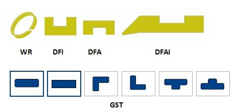
Profile shape matters as much as compound. Rectangular sections with chamfered or rounded edges are standard because a sharp corner digs into the groove fillet under load and starts a crack. Some designs add a groove or dimple pattern on the running face to retain oil; smooth faces give the lowest friction but the least tolerance for marginal lubrication. The profile codes in the image above — plain rectangular, grooved, and stepped variants — exist because the same compound behaves differently depending on where the load lands on the section.
Filled PTFE: Choosing the Right Filler
PTFE on its own is a poor bearing material. It creeps under load, has almost no wear resistance in dry sliding and expands about ten times as much as steel over a 100 °C rise. Fillers fix enough of that to make it the most widely used guide material in the industry, and the choice of filler is a genuine engineering decision.
Bronze raises compressive strength and thermal conductivity. Heat generated at the contact patch escapes into the bronze particles and out through the ring instead of building a hot spot on the surface. That is why bronze-filled grades dominate high-load hydraulic service. The trade-off is that bronze is harder than the bore in a marginal lubrication condition, and a run-dry event can polish or score a honed tube.
Carbon and graphite give the lowest friction and the best dry-running behaviour, plus antistatic properties that matter in explosive atmospheres and in some fuel systems. Load capacity is lower than bronze, so carbon grades suit high-speed, lower-pressure duty such as servo cylinders and water hydraulics.
Glass fibre is the cost option. It improves creep resistance and dimensional stability, works well up to about 3 m/s and is common in pneumatic and light hydraulic cylinders. Glass is abrasive against a hard chrome rod if the ring ever runs dry.

Two practical notes from incoming inspection. First, filler content is not visible, and two rings that look identical can differ by 15% bronze by weight. Ask for the compound designation and a batch certificate, not just “PTFE bronze”. Second, virgin PTFE should never be used as a guide ring regardless of how low the load is — it cold-flows out of the groove within months and the piston drops onto the bore.
Phenolic Fabric: Still the Heavy-Load Answer at Low Speed
Phenolic guide rings are made from cotton fabric impregnated with phenolic resin and cured under pressure into a dense laminate. The result is a hard, dimensionally stable ring with a compressive strength in the range of 300 N/mm² — several times what a filled PTFE compound can take — and a price that sits between PTFE and PEEK.
What it cannot do is run fast. The practical ceiling is around 0.5–1 m/s, and above that the friction heat has nowhere to go: phenolic is a poor conductor, the surface glazes, and the ring either wears rapidly or grabs. Temperature is the second limit; most fabric grades top out at 120–130 °C, which rules them out of hot hydraulic systems and most mobile equipment working near exhaust or brake heat.
Where phenolic earns its place is exactly where the alternatives fail: large bore cylinders with heavy side loads at low speed. Mining equipment, hydraulic presses, steel mill shears, gates and damper actuators. A 400 mm bore press cylinder with a 3 tonne moving assembly and a 30 mm/s closing speed is a phenolic application, and a bronze-filled PTFE ring in that position will deform and be squeezed out of the groove.

Fabric grades are also supplied as strip rather than finished rings, which matters for repair work: a maintenance team can cut and fit a strip on site without pressing the piston off the rod. Cutting accuracy then becomes the quality variable, and a rough cut with a 3 mm gap is a future failure.
PEEK: When Temperature and Chemistry Rule Out Both
PEEK sits above the other two on temperature and chemical resistance and below phenolic on pure compressive load. Unfilled PEEK runs to about 250 °C continuously, holds its modulus far better than PTFE at that temperature, and resists almost every hydraulic fluid, solvent and produced water chemistry except concentrated sulphuric acid and some halogens. Suppliers that mould or machine PEEK seals for oil and gas service, such as Precision Polymer Engineering, publish qualifying data against those fluids that is worth reading before a material is released to a drawing.
The applications where it is the only sensible answer share a pattern: high temperature plus a fluid that attacks or plasticises other polymers. Downhole tools and subsea hardware exposed to sour production fluids. Cryogenic transfer systems where PTFE becomes brittle and POM shatters. Semiconductor and analytical equipment where outgassing has to be minimal. Food and pharmaceutical lines that are steam or caustic cleaned daily.
Carbon-fibre reinforced PEEK extends the load range and is used in large cryogenic and LNG valve hardware, where the alternative is a metal guide with a lubrication problem. Glass-filled PEEK trades some strength for dimensional stability and cost.

The caution with PEEK is cost discipline. It is roughly three to five times the price of a bronze-filled PTFE ring at the same size, and it does not fix a groove that is 0.2 mm too deep or a bore with a 1.6 µm Ra and a visible tool mark. In our experience, about a third of the PEEK guide rings we quote as replacements are going into positions where the original failure had nothing to do with the material.
Groove and Wall Thickness: Where Most Guide Problems Start
The international reference for guide ring housings is ISO 10766:2014, Hydraulic fluid power — Cylinders — Housing dimensions for rectangular-section cut bearing rings for pistons and rods. It defines groove width, groove diameter and tolerances for bores from 16 mm to 500 mm and rods from 12 mm to 450 mm. It deliberately does not define the ring itself, because ring construction is manufacturer-specific. That split is the source of a common purchasing error: a buyer orders to ISO 10766 and assumes the ring will fit any groove made to the standard, when in fact the ring thickness has to match the specific groove depth of the series being used. Seal manufacturers such as Hallite publish their guide ring ranges against those housing series, which is the fastest way to check whether a groove on a drawing is a standard one.
Three dimensional rules decide whether the assembly works:
Radial thickness against groove depth. The ring should sit in the groove with a small controlled protrusion — enough to keep the piston off the bore, not enough to be crushed. If the ring is too thin, the piston touches the tube and the ring does nothing. If it is too thick, the ring is preloaded so heavily that friction rises, the groove wall yields, and in a gland the rod seal gets pinched. Thickness tolerance on machined rings is typically in the 0 to −0.05 mm band; anything looser and the protrusion varies around the circumference.
Band width against diameter. A working rule of thumb is a guide band width of at least 0.2 × rod diameter for rod guidance and 0.1 × piston diameter for piston guidance, with the length set by the bearing pressure calculation above. Narrow bands on large bores are the most common cause of piston cocking and one-sided seal wear.
Groove edge condition. Chamfer and deburr every groove edge. A raised burr on the groove side wall scores the ring as it is installed, and a sharp internal corner concentrates stress until the ring cracks at that point. Radius or chamfer the groove corners to match the ring’s edge treatment.
One more dimension that gets forgotten is the gap between the two guide bands on a piston. Placing them at the extreme ends of the piston gives the longest moment arm and the lowest bearing pressure. Placing them close together to “save space” doubles the load per band and lets the piston rock.
Cut Gap, Installation and the Bore It Runs Against
Guide rings are almost always split so they can be fitted over a piston without dismantling the rod. The gap in that split is a calculated dimension, not a manufacturing leftover.
Gap calculation. The ring expands with temperature and with fluid absorption. The minimum gap has to absorb that expansion plus the tolerance stack:
Z = π × (D − t) × ΔT × α + Zmin
where D is the groove diameter, t the ring thickness, ΔT the service temperature rise, α the coefficient of linear expansion and Zmin a small installation allowance. The expansion coefficient is where the materials diverge sharply: unfilled PTFE is around 12 × 10⁻⁵/K, PEEK around 4.7 × 10⁻⁵/K, and phenolic laminates lower still. A gap sized for PTFE in a PEEK ring is roughly three times larger than it needs to be, which costs contact area and bearing capacity.
Cut style. A straight butt cut is cheapest and the least stable: under load the two ends can overlap or separate. A 30° or 45° scarf cut gives a much more stable joint and is standard on better rings. Step cuts are used where the ring must not open at all under radial load.
Bore and rod finish. The counterface the guide runs on should be in the 0.2–0.6 µm Ra range for hydraulic service, honed rather than turned, with no spiral lead. A turned finish with a pronounced lead acts as a screw conveyor and pushes oil past the seal; a rough honed finish wears the ring and the seal together. Hard chrome on rods should be pore-free; porous chrome is a lap for the ring.
Installation. Warm the ring in oil or water to 80–100 °C if it is stiff, open it only as far as needed, and never use a sharp tool to lever it over a groove edge. Strip material is normally cut to length on site, and the cutting jig matters more than the knife: a mitre block that holds 45° gives a joint that closes properly, while a freehand cut leaves a gap that widens under load. Distributors that supply both strip and finished rings, ERIKS among them, usually stock the cutting tools as well. After fitting, check that the gap is even and that the ring rotates freely in its groove without rocking.
Failure Signatures and What They Tell You
When a cylinder comes back with a leaking seal and a worn guide, the guide is usually blamed. Reading the wear pattern tells you whether that is fair.
| What you see | Most likely cause | What to change |
|---|---|---|
| Even wear all round, ring thickness reduced, bore polished | Normal service life reached, or contaminated oil acting as lapping compound | Filtration, then replace — nothing else to fix |
| Heavy wear on one arc only, opposite side barely touched | Side load higher than designed, or single narrow band allowing cocking | Add a second band, widen bands, recalculate bearing pressure |
| Ring squeezed out of the groove, deformed edges, “mushroomed” section | Bearing pressure above the compound’s allowable load, or temperature above limit | Phenolic or PEEK, wider band, lower load |
| Ring split at the joint, gap closed to zero | Gap undersized for thermal expansion; ring ran hot | Recalculate Z, check cut style |
| Longitudinal cracks, glazed running surface | Phenolic ring run above its speed limit; friction heat | Switch to filled PTFE, reduce speed |
| Ring intact but seal extruded on one side | Guide protrusion too small — piston touching the bore, seal taking the gap | Correct ring thickness to groove depth |
| Black deposits, ring softened, dimensional growth | Fluid incompatibility — often ester or water-glycol against a PA or POM guide | Check fluid compatibility, change family |
The last row in that table is worth a comment. Guide materials are chosen for mechanical duty so often that fluid compatibility is treated as an afterthought. A nylon guide ring in a water-glycol system absorbs moisture, grows, closes its gap and seizes; a POM ring in a fire-resistant ester fluid softens. Both failures look like “cheap material” and are actually wrong material.
Specifying and Buying: Tolerances, Cut Type, Test Reports
Guide rings are low-cost parts with a disproportionate effect on warranty claims, and the purchase order is where that risk is controlled or lost. A specification that survives a supplier change needs five things on it:
- Compound, not colour. Write the filler type and content, for example “PTFE + 40% bronze, tensile strength 20 MPa minimum”. “PTFE bronze” on its own covers everything from 15% to 60% filler, and the difference shows up as a 50% change in wear rate.
- Dimensions with tolerances. OD, ID, thickness and width, each with its own band. Thickness at 0/−0.05 mm is typical for machined rings; anything looser and the protrusion varies around the circumference and the seal squeeze varies with it.
- Cut style. 45° scarf cut with a specified gap and a deburred edge. A butt cut is cheaper and opens under load; the wear pattern then moves to one side of the bore.
- Service conditions. Continuous and peak temperature, fluid name and concentration, side load estimate. Temperature and fluid decide the family; load only decides the width.
- Traceability. Batch code marked on the part, dimensional report per lot, material certificate. When a failure appears 18 months later, the batch code is the only link back to the compound that was actually used.
Packaging belongs on the list too. A guide ring stored bent in a bag takes a permanent set and will never run true again; flat packing with a moulding or cure date on the label is not too much to ask.
Two sourcing realities. First, the guide ring is the part where a distributor is most likely to substitute a cheaper compound without saying so, because nobody sees it once the cylinder is closed — the cross-reference tables that Seal Sales and similar houses publish are useful for identification, but they say nothing about compound. Second, lead time on phenolic and PEEK rings runs longer than on PTFE because the raw shapes are pressed and cured rather than extruded, so treat them as long-lead items when a cylinder is on a critical path.
Quick Reference: Which Guide for Which Duty
| Duty | First choice | Acceptable alternative | Avoid |
|---|---|---|---|
| Mobile hydraulic, 200–350 bar, 0.5 m/s, oil | Bronze-filled PTFE | Carbon-filled PTFE | Virgin PTFE, POM |
| Servo or proportional cylinder, low speed, precise motion | Carbon/graphite-filled PTFE | Bronze-filled PTFE with grooved face | Phenolic fabric (stick-slip) |
| Press or mining cylinder, heavy side load, under 0.3 m/s | Phenolic fabric | PEEK for higher temperature | Glass-filled PTFE |
| Water hydraulics or water-glycol | Bronze or carbon-filled PTFE | PEEK | PA, POM (moisture growth) |
| Above 150 °C or aggressive chemistry | PEEK | Carbon-filled PTFE to 250 °C | Phenolic, PA, POM |
| Cryogenic below −50 °C | Carbon-filled PTFE or PEEK | UHMWPE to −100 °C | Phenolic, POM |
| Pneumatic, dry air, cost-driven | Glass-filled PTFE or POM | PA | Phenolic (friction, no lubrication) |
Read the table as a starting point, then confirm with the bearing pressure calculation and the compound datasheet. The cases where a guide ring fails early are almost always the cases where the load was estimated rather than calculated, and the material was chosen from a catalogue page rather than from the duty. We cut guide rings and wear bands from stock strip and moulded shapes, and the machined PEEK and phenolic parts come off the same engineering plastics line. If the cylinder is already in service and leaking, the piston seal is usually the part that gets replaced first; check the guide before you put it back together, because a new seal on a cocked piston is a repeat repair. For the pressure side of the same problem, seal extrusion at high pressure covers how gap clearance and backup rings interact with what the guide is doing, and rod versus piston seal selection explains why the two positions need different guidance.
Guides, Bands and the Bore They Run In
Guide rings and wear bands in all four families this article compares are machined here: filled PTFE in glass, carbon, bronze and graphite grades, phenolic fabric laminate, PEEK and PEEK composites. Solid, split and stepped-cut forms, with wall thickness and cut gap made to the drawing rather than to the nearest stock size.
Guide problems start at the groove, so we check wall thickness against side load, cut gap against bore and temperature, and the lead-in chamfer against how the piston will actually be inserted. A guide ring 0.1 mm too thick does not fail at commissioning — it fails at the first hot cycle, and it takes the seal with it.
Send the side load, bore, stroke and temperature with the groove drawing to sales@bosssealing.com, and we will propose the family, the wall thickness and the cut, with price and lead time — normally within a day. The engineering review is free, and the contact form reaches the same engineers.