
High-pressure hydraulic leaks rarely announce their cause. The cylinder weeps past a seal that passed 100% of its incoming inspection, the replacement behaves identically, and the supplier takes the blame for a failure that lives in the hardware: the extrusion gap. Above roughly 100 bar, the clearance between seal and counterface becomes the design variable that decides seal life — before material brand, before hardness, before price. This article explains the extrusion mechanism, gives the gap and pressure numbers to design against, and covers the backup ring and profile choices that keep high-pressure seals out of the leak reports.
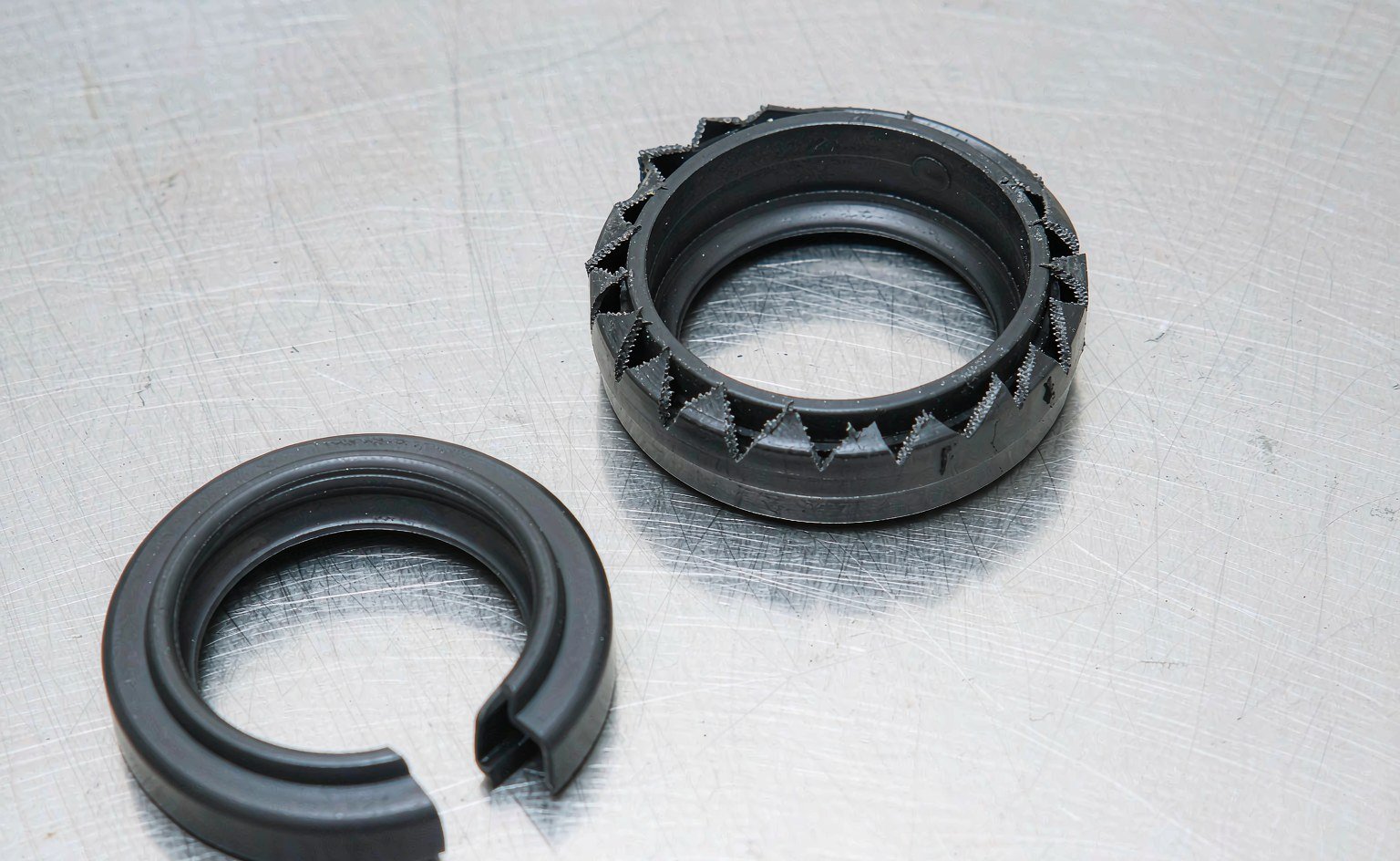
The Mechanism: How Pressure Converts a Seal Into Extruded Debris
An O-ring or lip seal under pressure behaves like a very viscous fluid. Pressure forces the elastomer toward any available escape route, and the only escape route in a normal gland is the radial clearance gap between the piston and bore, or between the rod and gland. Under sustained pressure the seal’s trailing edge deforms into that gap; under pressure cycling, the edge is repeatedly squeezed into the gap and dragged back out. The result is nibbling — a saw-tooth pattern of small tears along the seal’s low-pressure face, each cycle removing a sliver of material.
Nibbling is cumulative and self-accelerating. Each removed sliver enlarges the effective gap slightly, which lets the seal deform deeper on the next cycle. Left alone, the damage progresses from surface tears to a full chunk of the seal’s trailing edge, and the leak arrives quickly after that — a seal that ran clean at 150 bar for months can go from first weep to visible bypass in a few hundred pressure cycles once the extrusion damage is established.
Temperature and pressure interact because extrusion is a material-strength phenomenon. A seal compound softens as it heats; the same gap that a 90 Shore A polyurethane shrugs off at 40 °C becomes a failure driver at 100 °C when the compound’s modulus has dropped. This is why extrusion failures cluster on cylinders doing high-duty-cycle work in hot ambient — foundry auxiliaries, presses near furnaces, mobile equipment in summer — even though the pressure rating on the datasheet was never exceeded.
The Gap Is a Design Variable, Not a Tolerance Accident
The extrusion gap is the distance the seal can reach across, and it is set by diametral clearances, seal compression, bearing wear and deflection — not just by nominal machining. The design-relevant number is the maximum gap at operating conditions: bore at maximum tolerance plus bearing wear allowance, rod or piston at minimum, with the pressure side picked correctly. Published gland guidance, including the widely used O-ring groove design tables, gives maximum allowable gaps by compound hardness and pressure; the condensed version is below.
| System pressure | Recommended hardness | Max radial extrusion gap (single side) | Backup ring requirement |
|---|---|---|---|
| ≤ 50 bar (5 MPa) | 70 Shore A | ≤ 0.15 mm | Not required |
| 50–100 bar (5–10 MPa) | 70–90 Shore A | ≤ 0.10 mm | Optional static; recommended for high-frequency dynamic duty |
| 100–200 bar (10–20 MPa) | 90 Shore A | ≤ 0.08 mm | One ring on the low-pressure side (single-acting) |
| > 200 bar (20 MPa) | 90–95 Shore A or polyurethane | ≤ 0.05 mm | Both sides for double-acting positions |
Read the table against the pressure your system actually sees at the seal position, not the pump relief setting printed on the brochure. Pressure spikes count: a blocked-in line, a cold start against a loaded cylinder, or a regenerative circuit flip can put the seal at peak pressure for a fraction of a second per cycle — enough to drive nibbling, because the damage mechanism is per-cycle, not per-hour. Specify for the peak, and count the cycles.
Gap limits tighten further for soft compounds and thin cross-sections. A 70 Shore A NBR O-ring at 210 bar needs a gap below roughly 0.03 mm depending on cross-section — dimensions that few real assemblies hold — which is exactly why backup rings exist. The same O-ring with a backup ring on the pressure side bridges gaps several times larger, because the ring physically blocks the path into the gap.
Compound Choice: Hardness Is the First Line, Chemistry the Second
Within any seal family, higher hardness buys extrusion resistance because the compound resists the initial deformation into the gap. That is why 90 Shore A NBR and FKM exist, and why high-pressure hydraulic lip seals are almost universally 90+ Shore A polyurethane — PU’s combination of hardness, tear strength and abrasion resistance makes it the default rod and piston seal material above 150 bar in mobile and industrial cylinders.
But hardness is not a substitute for gap control, and it carries costs. Harder compounds seal on worse surfaces less forgivingly, run with higher friction, and lose low-temperature flexibility. The correct sequence is: control the gap by design first, add a backup ring where the gap cannot be tightened, and select the compound for the fluid, temperature and wear environment — with hardness as the extrusion-resistance lever once those are fixed. Suppliers such as Hallite publish pressure-versus-gap limits for their profiles; use the profile-specific data rather than generic O-ring tables when you are specifying shaped seals, because lip geometry changes how pressure loads the trailing edge.
| Compound | Typical hardness | Extrusion resistance | Where it fits |
|---|---|---|---|
| NBR | 70–90 Shore A | Moderate at 90 A; poor at 70 A under 150+ bar | General hydraulics up to ~150 bar with backup rings |
| HNBR | 70–90 Shore A | Similar to NBR with better heat and additive tolerance | Hot hydraulic circuits, additive-heavy fluids |
| Polyurethane (AU) | 90–95 Shore A | Excellent — the high-pressure hydraulic default | Rod and piston seals, 200–400 bar duty |
| FKM | 75–90 Shore A | Good at high hardness, temperature-limited otherwise | Hot, chemically aggressive hydraulic media |
| PTFE with backup | N/A (filled grades) | Excellent with anti-extrusion hardware | Chemical service, high temperature, low friction |
Backup Rings: Placement Rules and the Mistakes That Cancel Them
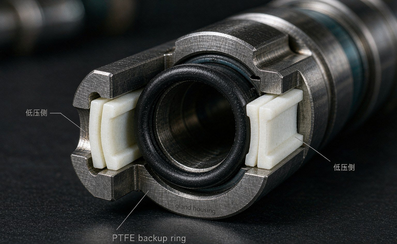
A backup ring is a rigid washer — PTFE, nylon, PEEK or hard polyurethane — seated in the gland on the low-pressure side of the O-ring, closing the extrusion gap so the elastomer has nowhere to go. The rules that matter are all positional. Single-acting pressure gets one ring on the low-pressure side, which is the side opposite the pressure: getting the side wrong puts the ring where it does nothing while the O-ring nibbles on the unprotected side. Double-acting positions get rings on both sides. The rings must be scarf-cut or split so they can be installed around a shaft without stretching the O-ring over them, and they must leave a small circumferential gap for thermal expansion — a PTFE ring installed with no clearance will bind and load the O-ring unevenly.
Three installation mistakes cancel the hardware you paid for. Rings installed backward (beveled face toward the seal instead of away) can cut the O-ring edge they were meant to protect. Rings omitted during a field reseal because “it went together fine without them” — until the next teardown finds the O-ring chewed. And rings from the wrong material that swell in the system fluid and close up their own expansion gap; a nylon ring in hot water-based fluid behaves differently than in mineral oil, so the ring material gets the same compatibility check as the seal.
One further design note: adding backup rings widens the required gland. Grooves converted from plain O-ring to backed O-ring need the width recalculated against the supplier’s gland tables; forcing the assembly into the old groove overfills it and creates a different failure — shear of the compound at the parting line — that gets misdiagnosed as a material problem. Our backup ring and washer range covers the common sizes in PTFE, nylon and harder compounds, and the gland-width recalculation is the first thing we check when a customer’s converted gland starts failing.
When the O-Ring Is the Wrong Profile: T-Seals and Shaped Seals
Above the gap-control capability of a backed O-ring, the profile family changes rather than the compound. T-seals — a T-shaped elastomer core flanked by two rigid backup rings — put the anti-extrusion hardware in the profile itself. The rings ride the full pressure load and cannot shift, which lets a T-seal bridge gaps far beyond O-ring limits at the same pressure. They are the standard answer on high-pressure valve stems, wellhead equipment and presses where clearances are set by wear rather than machining.
For reciprocating rod and piston duty at 200–400 bar, dedicated polyurethane hydraulic profiles (with their own pressure-support geometry) usually beat any O-ring arrangement on both life and friction. The trade is housing standardization: O-rings and T-seals fit ISO and AS568 glands that every cylinder shop can machine, while dedicated PU profiles lock you to specific housing standards — usually the right trade on new designs, the wrong one on repairs. Where a repair must fit an existing machined gland, our piston seal and rod seal ranges cover the standard housing families, and the combined rod/piston category lists the profiles that serve both positions in a common housing.
Diagnosing an Extrusion Leak From the Failed Part
The failed seal carries its own report. The signatures below separate extrusion from the other high-pressure leak causes in one teardown.
| Signature on the failed seal | Cause | Correct fix |
|---|---|---|
| Saw-tooth nibbles on the low-pressure trailing edge | Extrusion gap too large for pressure/hardness | Tighten gap, add or reposition backup ring, raise hardness |
| Chunk missing from trailing edge, sharp fracture faces | Extrusion advanced to failure; check peak pressure events | Same as above, plus peak-pressure audit (spikes, cold starts) |
| One-sided wear, opposite side intact | Bearing wear or misalignment — seal carrying side loads | Replace wear rings/bearings; check gland concentricity |
| Uniform wear, polished counterface, short life | Counterface finish or hardness degraded | Re-machine or sleeve the counterface; seal swap will not help |
| Soft, swollen seal, damage follows swelling | Fluid incompatibility enlarged the seal into a fixed gap | Compound change for the actual fluid, including top-up fluids |
| Fracture at parting line, gland visibly overfilled | Backup rings added without widening the groove | Recalculate gland width per supplier tables |
The single most useful habit: photograph the seal in place before removal, and note which side the damage is on. “Extrusion” damage on the pressure side instead of the trailing edge means the diagnosis is not extrusion at all — it is reverse-pressure damage, and the fix is a double backup or a pressure-balanced profile, not tighter gaps.
Peer references for gap tables and pressure ratings include the distributor catalogs at CNL Seals, the compound and profile data libraries published by seal makers such as Trelleborg, and the general fluid-power background at The Engineering ToolBox.
FAQ
At what pressure does an O-ring actually need a backup ring? The honest answer is gap-dependent, not a single number. As a working rule, 70 Shore A compounds start needing protection around 50–100 bar in realistic gaps, 90 Shore A around 100–200 bar, and anything above 200 bar should assume backup rings on the pressure-bearing sides. If your measured maximum gap at operating temperature exceeds the table value for your hardness and pressure, the ring goes in regardless of the pressure number.
Can I just use a harder O-ring instead of backup rings? Sometimes, at moderate pressures. Moving from 70 to 90 Shore A roughly doubles the allowable gap at the same pressure, and it is the cheapest fix where the gap is marginal. But hardness does not scale far: above 200 bar, even 90 Shore A compounds need gap values most assemblies cannot hold without a backup ring, and the harder compound costs you friction and low-temperature performance.
Which side does the backup ring go on? The low-pressure side — opposite the pressure — where the O-ring would otherwise deform into the gap. In single-acting grooves that is one ring; in double-acting grooves, one ring per side. If a teardown finds extrusion damage on the side you thought was protected, the ring was on the wrong side or the pressure direction was different from the drawing.
Why does the seal leak only after the system warms up? Two reasons stack. Diametral clearances grow as the housing heats relative to the seal’s environment, widening the effective extrusion gap; and the compound softens, lowering its extrusion resistance at exactly the moment the gap grew. A cylinder that seals cold and weeps hot is showing you a gap-and-temperature problem — measure the cold clearances, add thermal growth, and check the result against the gap table at operating temperature.
Do pressure spikes matter if the average pressure is well under the limit? Yes — extrusion damage accumulates per cycle, not per hour. A system that spikes to 250 bar once per cycle at an average of 120 bar damages a marginal seal exactly as a continuous 250 bar service would, just spread over more cycles. Specify gaps and hardware for the peak, and count cycles when estimating life.
Gap, Ring and Profile, Solved Together
Extrusion is a system failure, so the parts we quote for it come as a set: back-up rings in filled PTFE and carbon-filled PEEK, T-seals and shaped seals where the O-ring profile is the wrong answer, and the O-rings or U-cups underneath them in NBR, PU and FKM — machined or molded to the gland you have rather than to a nominal series.
The number that decides the quote is the gap: diametral clearance at temperature, not at 20 °C. We ask for it, along with pressure spikes and cycle count, then propose ring hardness, the number of rings, and the corner radius that lets the elastomer flow into the gap without being cut. Where the hardware cannot be changed the seal has to be, and we will say which route is cheaper.
Send the failed part, the groove dimensions and the pressure trace to sales@bosssealing.com, and you will get a diagnosis in the same terms this article uses, plus a proposed stack, price and lead time. Usually within 24 hours; the engineering review is at no charge, through the contact form as well.