
Вращающееся уплотнение вала выбирают на трёх уровнях: материал кромки, конструкция уплотнения и состояние вала — и большинство возвратов по протечкам восходит к решению, пропущенному на одном из этих уровней. Таблица материалов идёт первой, потому что температура и окружная скорость отсеивают быстрее всего остального. Семейство конструкций — эластомерная кромка, кромка из PTFE или кассетное уплотнение — идёт вторым. Вал идёт последним на чертеже, но первым в статистике отказов: правильное уплотнение, работающее по плохой контрповерхности, всё равно течёт. Это руководство проходит все три уровня в том порядке, в котором выбор происходит на самом деле, с теми цифрами, которые мы используем на стенде, когда заказчик присылает нам чертёж вала и рабочий диапазон.
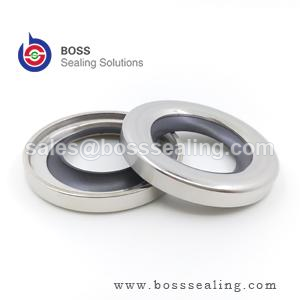
Что на самом деле делает кромка
Радиальная кромка уплотнения не создаёт контакта металла с резиной по смоченной поверхности. При надлежащих условиях кромка скользит по гидродинамической масляной плёнке толщиной примерно 1–3 мкм, которая создаётся вращением вала и стабилизируется микроскопическим рельефом шероховатости поверхности вала. Задача уплотнения — удерживать эту плёнку нужной толщины: слишком толстая плёнка — и масло выкачивается за кромку; плёнка схлопывается — и кромка работает в граничном контакте при каждом пуске, изнашивая себя и вал. Контактная полоса намеренно узкая — несколько десятых миллиметра — чтобы радиальная нагрузка сосредоточивалась в устойчивом мениске со стороны воздуха.
Отсюда следуют два вывода, и они определяют всё остальное в этой статье. Во-первых, тепло трения выделяется в очень малом объёме: граница кромки обычно на 15–40 °C горячее основной массы жидкости, а значит, масляная ванна при 90 °C уже требует от кромки из NBR выживания вблизи её материального предела 100 °C. Во-вторых, поверхность вала — не пассивный наблюдатель: это половина трибологической системы, и её чистота, твёрдость и рисунок шлифования решают, может ли эта масляная плёнка вообще существовать.
Четыре материала кромки и их рабочие диапазоны
Материал кромки — первый фильтр, потому что он наименее поддаётся компромиссу. Опубликованные данные производителей (включая широко цитируемые каталожные пределы Trelleborg и других производителей уплотнений — см. ассортимент вращающихся уплотнений Trelleborg для актуальных технических листов семейств) сходятся к диапазонам, приведённым ниже.
| Материал кромки | Непрерывная температура | Макс. окружная скорость | Совместимость с присадками EP/AW | Работа без смазки |
|---|---|---|---|---|
| NBR (нитрил) | От −40 до +100 °C | ~12–14 м/с | Удовлетворительная — набухает в агрессивных маслах типа GL-5 | Плохо |
| ACM (полиакрилат) | −20…+150 °C | ~18 м/с | Отличная — материал для EP-присадок | Плохо |
| FKM (фторэластомер) | −30…+200 °C | ~35 м/с | Хорошая — проверяйте на горячих синтетических маслах с высоким содержанием присадок | Удовлетворительно |
| Кромка из PTFE | −60…+250 °C | 40+ м/с | Практически инертна | Отлично |
Читайте таблицу как лестницу отсева. Масло при 110 °C исключает NBR независимо от того, насколько мягка скорость. Редуктор, работающий на синтетическом масле с высоким содержанием присадок при температуре, резко сокращает срок службы NBR — ACM или FKM обычно служат в два-три раза дольше в том же корпусе, и именно здесь разница в цене материала окупается за счёт предотвращённых простоев. Кромки из силикона существуют для специальных и пищевых применений, но их механическая износостойкость ограничена при непрерывной вращательной работе, поэтому мы считаем их нишевым решением, а не строкой таблицы.
Скорость — первый настоящий расчёт
Выживает ли кромка, решает окружная скорость, а не число оборотов. Расчёт занимает одну строку:
v = π × d × n / 60 000 (м/с), где d — диаметр вала в миллиметрах, а n — скорость в об/мин.
Вал 45 мм при 1450 об/мин даёт v = 3,4 м/с — комфортно для NBR. Тот же вал 45 мм на конце двигателя при 3600 об/мин даёт 8,5 м/с — всё ещё в пределах диапазона NBR, но тепло трения теперь поднимает границу кромки на 30 °C и более выше ванны, так что ванна при 90 °C уже не является применением для NBR. Шпиндель 25 мм при 12 000 об/мин даёт 15,7 м/с — выше любого эластомера, кроме FKM, и на пределе даже для него; это территория кромки из PTFE.
Стандартные справочные значения, включая требования к чистоте поверхности и твёрдости, построенные вокруг них, задокументированы в ISO 6194-1 и DIN 3760 и перекрёстно связаны с практическими инженерными ресурсами, такими как The Engineering ToolBox. Когда расчётная скорость превышает 12–15 м/с, переходите на FKM; выше примерно 20 м/с указывайте кромку из PTFE и соответствующим образом подготавливайте контрповерхность вала.
Конструкции эластомерных кромок: что делают пружина и пыльник
Классическое эластомерное радиальное уплотнение вала — металлический каркас, обрезиненная наружная поверхность, браслетная пружина, обрезанная кромка — остаётся стандартом для подавляющего большинства вращательных применений при давлении примерно до 0,5 бар. Каждый компонент оправдывает своё место. Браслетная пружина поддерживает постоянную радиальную нагрузку по мере износа кромки, остаточной деформации от теплового старения или небольших перекосов вала; кромка, которая “на ощупь плотная” без своей пружины, теряет контактное давление в течение нескольких недель при температуре. Обрезиненная наружная поверхность уплотняет по расточке корпуса, обработка которой никогда не бывает такой гладкой, как заявлено на чертеже, и компенсирует разницу теплового расширения между алюминиевым корпусом и стальной вставкой.
Два конструктивных улучшения покрывают большинство эксплуатационных условий. Вторая, обращённая наружу пылевая кромка удерживает брызги, абразив и воду от мойки вдали от основной кромки — но она удваивает трение на границе, а значит, снижает скоростную способность; применяйте уплотнение с пыльником на один скоростной класс ниже. Там, где давление превышает примерно 0,5 бар — корпуса насосов, полости двигателей, планетарные ступицы — стандартная кромка отгибается или протирается насквозь. Разгруженные по давлению конструкции с усиленной, более короткой кромкой выдерживают несколько бар; сверх этого правильный ответ — торцевое уплотнение, а не кромка побольше.
Уплотнения с кромкой из PTFE: где они оправдывают свою цену
Кромки из PTFE переворачивают логику уплотнения. PTFE нельзя формовать как резину, поэтому кромку точно обрабатывают из спечённой или шнеково-экструдированной заготовки и механически закрепляют в каркасе. Браслетной пружины нет: кромка сформирована с геометрией натяга, которая полагается на собственную изгибную память — кромка “с памятью формы” — для поддержания контакта. Контактная полоса гораздо шире, чем у эластомерной кромки, с гораздо меньшей удельной нагрузкой, и именно это позволяет достигать окружных скоростей свыше 35–40 м/с и непрерывных температур до 250 °C с кратковременными более высокими. Материал практически инертен к растворителям, кислотам, топливам и большинству технологических сред, и он выдерживает сухие пуски, которые уничтожили бы кромку из NBR или FKM за минуты.
Высокоэффективные конструкции кромок из PTFE — зрелая, задокументированная инженерная область — специалисты, такие как Precision Polymer Engineering публикуют диапазоны, которые мы здесь обобщаем — и наша собственная линейка пружинно-нагруженных уплотнений из PTFE охватывает вращающиеся и качающиеся варианты, где полимерная кромка плюс металлическая пружина полностью заменяют эластомер.
Честная колонка: кромки из PTFE стоят в несколько раз дороже своих эластомерных аналогов, они менее терпимы к биению вала, рисунку шлифования и дефектам поверхности, потому что жёсткая кромка не может подстроиться, а повреждения при монтаже менее ремонтопригодны — зазубренная кромка из PTFE не восстанавливается так, как частично восстанавливается резина. Указывайте PTFE, когда скорость, температура или химия действительно исключают эластомер; избыточное указание PTFE для умеренного редуктора на 4 м/с ничего не даёт.
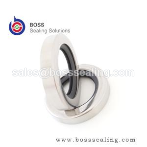
Вал — это половина уплотнения
Ни одна таблица материалов не выдержит плохой контрповерхности. Требования ниже взяты из практики ISO 6194 и являются значениями, которые мы наносим на чертежи для поставщиков.
| Параметр вала | Эластомерная кромка | Кромка из PTFE | Почему это важно |
|---|---|---|---|
| Шероховатость поверхности Ra | 0,2–0,8 мкм | 0,1–0,4 мкм | Too rough abrades the lip; too smooth cannot hold the oil film |
| Counterface hardness | ≥ 45 HRC | ≥ 50 HRC | Below this, the lip machines a wear groove into the shaft |
| Grit-contaminated duty | 55+ HRC or hardened sleeve | Hardened sleeve preferred | Embedded grit turns the lip into a lapping tool |
| Plunge grinding | Required — no machine lead | Required, finer | A helical grinding pattern pumps oil out like an Archimedes screw |
| Runout and misalignment | Per ISO 6194 limits | Tighter — rigid lip will not conform | Excess runout breaks the meniscus on the air side each revolution |
Two shaft-side notes save real money. First, a shaft that has already run a seal for years usually carries a wear groove at the lip position; fitting the new seal on the old groove leaks from the first rotation. The cheapest correct fix is a thin-wall repair sleeve pressed over the shaft to a fresh diameter — a standard catalog item, not a machining job. Second, when a housing is reworked, check that the bore chamfer still leads the seal in square; a seal entered crooked damages its own lip before the machine ever runs.
Matching the Design Family to the Duty
| Duty | First choice | Alternative | Обоснование |
|---|---|---|---|
| Clean industrial gearbox, oil < 90 °C, v < 8 m/s | NBR single lip | FKM for long service life | Cost-optimized; NBR fully inside its envelope |
| EP-additized synthetic oil, sump 100–140 °C | ACM | FKM | ACM exists for additive resistance; FKM wins on speed |
| v = 15–35 m/s, hot sump | FKM, hardened shaft | PTFE lip above 35 m/s | Friction heat, not fluid, is the failure driver |
| Aggressive media, dry start-ups, v > 35 m/s | Кромка из PTFE | Spring-energized PTFE | Only family with the temperature and chemical headroom |
| Wheel hubs, track drives, slurry, washdown | Cassette seal | Double lip + V-ring flinger | Contamination path must be a labyrinth, not a line |
| Pressure > 0.5 bar at the seal | Pressure-balanced lip design | Mechanical face seal | Standard lips blow open under sustained pressure |
Third-party catalogs such as Seal Sales и Darcoid are useful for cross-referencing common inch and metric sizes once the design family is decided — sizing is the easy part; the family choice above is what prevents the repeat leak.
Pressure, Vacuum and the Edges of the Lip Family
Pressure capability deserves its own paragraph because it is the most commonly misread column in seal catalogs. A conventional lip seal is a low-pressure device: the lip is designed to run against a flooded, essentially unpressurized sump, and sustained pressure above roughly 0.5 bar forces the lip against the shaft hard enough to tear the oil film and burn the contact band. Pressure-balanced lips — shorter, wider, backed by a full rubber face — push that boundary to around 5 bar in the better designs; beyond that, the conversation moves to mechanical face seals or packed glands, which distribute the load over faces designed for it. The corollary: if the pressure at the seal position is intermittent — pressure spikes from thermal expansion in a blocked-in line, for example — specify for the peak, not the average, because a lip fails in seconds at peak, not over months of average.
Vacuum runs the same physics in reverse and adds one demand: the seal must not admit air. For vacuum service, the lip faces the wrong direction or a double-lip arrangement seals both ways, and the shaft finish tightens toward the smooth end of the Ra band — but not past it, because a too-smooth shaft cannot hold the micro-oil film even at low speed, and the lip chatters. High-vacuum rotary duties are a PTFE-lip and spring-energized specialty for good reason; the elastomer families keep their properties down to rough vacuum but outgas and age differently at the deep end.
Speed at very small diameters and very large diameters also warps the standard table. Small shafts under 10 mm run light lips with little thermal mass — they overheat at speeds the table says are comfortable, because the published limits assume the heat sink of a mid-range diameter. Large shafts above 300 mm reverse the problem: peripheral speed is easy to satisfy, but runout, deflection and handling damage dominate, and the seal selection conversation becomes a housing-stiffness conversation. Neither extreme is exotic — mixer drives and calendar rolls live there — and both are the cases where a standard catalog pick most often needs an engineer’s override.
Reading a Failed Rotary Seal Before You Order the Replacement
The failed seal is a forensic report, and it is free. Read it before ordering, or the replacement inherits the same death. Lip hardened and cracked radially: thermal aging — the material ran past its temperature, usually because bulk sump temperature was mistaken for lip temperature; recheck the material row, not the brand. Lip worn on one side only, opposite side unworn: misalignment or bore-to-shaft misalignment beyond the runout limits — the seal was correct, the housing survey was not. Lip worn evenly but short life with a polished shaft wear track below the contact band: the shaft lost its hardness or the finish degraded through the wear groove; a repair sleeve is the fix, another seal is not. Swollen and soft lip: fluid incompatibility — check what actually went into the sump, because top-up fluids are the usual culprit when a seal that ran for years suddenly swells. Blistered or carbonized PTFE lip face: dry running or gross lubrication loss — investigate the oil level logic and the start-up procedure, because no material survives genuine dry rotation indefinitely. Extruded or rolled back on the pressure side: pressure exceeded the design — the duty changed even if the machine did not, and the answer is a pressure-balanced design or a mechanical seal.
Two inspection habits make this diagnosis reliable. Photograph the seal in the housing before removing it — the position of debris, the side of wear and the oil condition all change once the part comes out. And cut one worn lip in half: the contact band width and the subsurface cracking pattern distinguish heat aging from mechanical wear in ten seconds, which is the difference between ordering the same seal again and actually fixing the account.
Installation and the First Hour
Most rotary seals are killed during installation, not in service. Three disciplines prevent it. First, entry: the housing bore chamfer and the shaft end chamfer must lead the seal square; a seal entered cocked scrapes its own lip on the shaft keyway or thread, and the damage is invisible once the seal is home. Use an installation tool that pushes on the seal’s rigid case, never on the rubber face, and support the bore on the opposite side so the case cannot deform. Second, lubrication: wipe the lip and the shaft with the working fluid — never grease on a seal destined for oil service in a high-speed duty, because grease-lubricated start-ups run boundary contact far longer. Third, spring discipline: garter springs shift in transit; verify the spring is seated after handling, because a spring that pops out in the box is a seal that leaks in the first hour.
The first hour of running is part of the specification. Run the machine and check for weep at the shaft — a slight oil mist at the lip is normal during the first minutes as the seal laps itself in, but a drip within the first hour means the seal comes out and the diagnosis starts from the failure table above. Machines started on low oil level, cold oil or blocked breathers fail seals in that first hour at rates that no material selection can offset.
A Selection Workflow That Holds Up
Run the decision in this order and most seal problems never reach the machine. One: write down bulk fluid temperature, peripheral speed and media chemistry — the material table disqualifies before design matters. Two: check the pressure at the seal position; above ~0.5 bar, the standard lip family is out and the budget shifts. Three: classify the contamination — splash versus immersion versus slurry — and let that pick single lip, double lip or cassette. Four: audit the shaft with the table above, including a lead-pattern check on any reground surface. Five: only now open size catalogs. For non-standard bore or shaft dimensions, our rotary oil seal range covers the common ISO sizes and custom diameters, and our rubber seals line и high/low temperature seal range cover the elastomer variants in the material table. Where the envelope falls off every standard chart — combined speed, temperature and media — we design the lip to the duty through our customized products channel, which in practice is how most OEM spindle and mixer accounts end up specified.
Главный вывод
Select lip material from temperature and peripheral speed, select the design family from pressure and contamination, and then spend the remaining attention on the shaft — because the oil film the seal needs to survive exists only on a correctly finished, sufficiently hard, lead-free counterface. Get those three in that order and the seal becomes the boring, forgettable component it is supposed to be. Skip the shaft audit or let bulk sump temperature stand in for lip temperature, and no brand of seal will fix what the specification broke.
Lip Seals Matched to the Shaft
Rotary shaft seals are quoted against the shaft, not against a size list: PTFE lip seals for the speed and chemical envelope this article sets out, elastomer lip seals in NBR, FKM and silicone with the spring and dust lip the duty calls for, and cassette designs where contamination is the design case rather than an afterthought. Non-standard sizes are machined or molded to the housing and shaft dimensions you measure.
Before a lip material is proposed we ask for five numbers: shaft hardness, surface finish Ra, runout, speed at the lip, and the pressure the seal actually sees. Those decide whether a PTFE lip earns its price or an elastomer lip is simply correct. Where a shaft is marginal we say so, because no lip survives a counterface that was not finished for it.
Send the housing and shaft drawing, the speed and the medium to sales@bosssealing.com, and we will return the design family, compound and price with the shaft requirements written out. Replies usually within a day; the engineering review is free, and the форму обратной связи поступают обращения.