
A rotary shaft seal is chosen at three levels: lip material, seal design and shaft condition — and most leak returns trace back to a decision skipped at one of those levels. The material table comes first because temperature and peripheral speed disqualify faster than anything else. The design family — elastomer lip, PTFE lip or cassette — comes second. The shaft comes last on the drawing but first in the failure statistics: a correct seal running on a bad counterface still leaks. This guide walks through all three in the order a selection actually happens, with the numbers we use on the bench when a customer sends us a shaft drawing and an operating envelope.
What the Lip Is Actually Doing
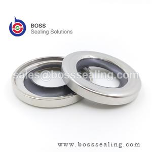
A radial lip seal does not make metal-to-rubber contact across a wet surface. Under proper conditions the lip rides on a hydrodynamic oil film roughly 1–3 µm thick, generated by shaft rotation and stabilized by the microscopic asperity pattern of the shaft surface. The seal’s job is to hold that film at the correct thickness: film too thick and oil pumps out past the lip; film collapses and the lip runs boundary contact at every start-up, wearing itself and the shaft. The contact band is deliberately narrow — a few tenths of a millimeter — so the radial load concentrates into a stable meniscus on the air side.
Two consequences follow, and they drive everything else in this article. First, friction heat is generated in a very small volume: the lip interface typically runs 15–40 °C hotter than the bulk fluid, which means an oil sump at 90 °C is already asking an NBR lip to survive near its 100 °C material limit. Second, the shaft surface is not a passive bystander — it is half of the tribological system, and its finish, hardness and grinding pattern decide whether that oil film can exist at all.
The Four Lip Materials and Their Envelopes
Lip material is the first filter because it is the least negotiable. Published manufacturer data (including widely cited catalog limits from Trelleborg and other seal producers — see the Trelleborg rotary seal range for current family datasheets) converge on the envelopes below.
| Lip material | Trochgeande temperatuer | Max peripheral speed | EP/AW additive compatibility | Dry running |
|---|---|---|---|---|
| NBR (nitril) | −40 oant +100 °C | ~12–14 m/s | Fair — swells with aggressive GL-5 type oils | Min |
| ACM (polyacrylate) | −20 to +150 °C | ~18 m/s | Excellent — the EP-additive material | Min |
| FKM (fluor-elastomear) | −30 to +200 °C | ~35 m/s | Good — verify with hot, highly additized synthetics | Redlik |
| PTFE lip | −60 to +250 °C | 40+ m/s | Essentially inert | Poardebêst |
Read the table as a disqualification ladder. Bulk oil at 110 °C removes NBR no matter how gentle the speed. A gearbox running a highly additized synthetic at temperature shortens NBR life dramatically — ACM or FKM typically lasts two to three times longer in the same housing, which is where the material price difference pays for itself in avoided stoppages. Silicone lips exist for specialty and food applications but their mechanical wear resistance is limited in continuous rotary duty, so we treat them as a niche call rather than a table row.
Speed Is the First Real Calculation
Peripheral speed, not RPM, decides whether a lip survives. The calculation takes one line:
v = π × d × n / 60,000 (m/s), where d is shaft diameter in millimeters and n is speed in RPM.
A 45 mm shaft at 1450 RPM gives v = 3.4 m/s — comfortable for NBR. The same 45 mm shaft on a motor extension at 3600 RPM gives 8.5 m/s — still inside NBR’s envelope, but the friction heat now pushes the lip interface 30 °C or more above the sump, so a 90 °C sump is no longer an NBR application. A 25 mm spindle at 12,000 RPM gives 15.7 m/s — past every elastomer except FKM, and marginal even there; this is PTFE-lip territory.
The standard reference values, including the surface-finish and hardness requirements built around them, are documented in ISO 6194-1 and DIN 3760, and cross-referenced by practical engineering resources such as The Engineering ToolBox. When a calculated speed lands above 12–15 m/s, move to FKM; above roughly 20 m/s, specify a PTFE lip and prepare the shaft counterface accordingly.
Elastomer Lip Designs: What the Spring and the Dust Lip Do
The classic elastomer radial shaft seal — metal case, rubbercovered OD, garter spring, trimmed lip — remains the default for the overwhelming majority of rotary duties under about 0.5 bar of pressure. Each component earns its place. The garter spring maintains constant radial load as the lip wears, takes a compression set from heat aging, or rides out minor shaft misalignment; a lip that “feels tight by hand” without its spring loses contact pressure within weeks at temperature. The rubber OD seals against housing bore machining that is never as smooth as the drawing claims, and it accommodates the thermal expansion difference between an aluminum housing and a steel insert.
Two design upgrades cover most field conditions. A second, outward-facing dust lip keeps splash, grit and washdown water away from the primary lip — but it doubles friction at the interface, so it costs speed capacity; run a dust-lipped seal one speed class down. Where pressure exceeds roughly 0.5 bar — pump cases, motor cavities, planetary hubs — a standard lip blows open or wears through. Pressure-balanced designs with a reinforced, shorter lip handle several bar; beyond that the correct answer is a mechanical face seal, not a bigger lip.
PTFE Lip Seals: Where They Earn Their Price
PTFE lips flip the sealing logic. PTFE cannot be molded like rubber, so the lip is precision-machined from a sintered or ram-extruded blank and mechanically retained in the case. There is no garter spring: the lip is formed with an interference geometry that relies on its own flexural memory — the “memory-set” lip — to maintain contact. The contact band is much wider than an elastomer lip’s, with far lower unit load, which is exactly what allows surface speeds past 35–40 m/s and continuous temperatures to 250 °C with short excursions higher. The material is essentially inert to solvents, acids, fuels and most process media, and it tolerates dry start-ups that would destroy an NBR or FKM lip in minutes.
High-performance PTFE lip designs are a mature, documented engineering field — specialists such as Precision Polymer Engineering publish the envelopes we summarize here — and our own PTFE spring-energized seal line covers the rotating and oscillating variants where a polymer lip plus metal spring replaces elastomer entirely.
The honest column: PTFE lips cost several times their elastomer equivalents, they are less forgiving of shaft runout, lead pattern and surface defects because the rigid lip cannot conform, and installation damage is less repairable — a nicked PTFE lip does not recover the way rubber partially does. Specify PTFE when speed, temperature or chemistry actually disqualifies elastomer; over-specifying it on a moderate 4 m/s gearbox duty buys nothing.
The Shaft Is Half the Seal
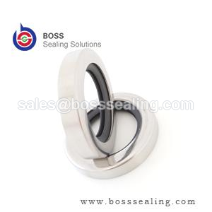
No material table survives a bad counterface. The requirements below come from ISO 6194 practice and are the values we put on supplier drawings.
| Shaft parameter | Elastomer lip | PTFE lip | Wêrom't it útmakket |
|---|---|---|---|
| Surface roughness Ra | 0.2–0.8 µm | 0.1–0.4 µm | Too rough abrades the lip; too smooth cannot hold the oil film |
| Counterface hardness | ≥ 45 HRC | ≥ 50 HRC | Below this, the lip machines a wear groove into the shaft |
| Grit-contaminated duty | 55+ HRC or hardened sleeve | Hardened sleeve preferred | Embedded grit turns the lip into a lapping tool |
| Plunge grinding | Required — no machine lead | Required, finer | A helical grinding pattern pumps oil out like an Archimedes screw |
| Runout and misalignment | Per ISO 6194 limits | Tighter — rigid lip will not conform | Excess runout breaks the meniscus on the air side each revolution |
Two shaft-side notes save real money. First, a shaft that has already run a seal for years usually carries a wear groove at the lip position; fitting the new seal on the old groove leaks from the first rotation. The cheapest correct fix is a thin-wall repair sleeve pressed over the shaft to a fresh diameter — a standard catalog item, not a machining job. Second, when a housing is reworked, check that the bore chamfer still leads the seal in square; a seal entered crooked damages its own lip before the machine ever runs.
Matching the Design Family to the Duty
| Duty | First choice | Alternative | Redenearring |
|---|---|---|---|
| Clean industrial gearbox, oil < 90 °C, v < 8 m/s | NBR single lip | FKM for long service life | Cost-optimized; NBR fully inside its envelope |
| EP-additized synthetic oil, sump 100–140 °C | ACM | FKM | ACM exists for additive resistance; FKM wins on speed |
| v = 15–35 m/s, hot sump | FKM, hardened shaft | PTFE lip above 35 m/s | Friction heat, not fluid, is the failure driver |
| Aggressive media, dry start-ups, v > 35 m/s | PTFE lip | Spring-energized PTFE | Only family with the temperature and chemical headroom |
| Wheel hubs, track drives, slurry, washdown | Cassette seal | Double lip + V-ring flinger | Contamination path must be a labyrinth, not a line |
| Pressure > 0.5 bar at the seal | Pressure-balanced lip design | Mechanical face seal | Standard lips blow open under sustained pressure |
Third-party catalogs such as Seal Sales en Darcoid are useful for cross-referencing common inch and metric sizes once the design family is decided — sizing is the easy part; the family choice above is what prevents the repeat leak.
Pressure, Vacuum and the Edges of the Lip Family
Pressure capability deserves its own paragraph because it is the most commonly misread column in seal catalogs. A conventional lip seal is a low-pressure device: the lip is designed to run against a flooded, essentially unpressurized sump, and sustained pressure above roughly 0.5 bar forces the lip against the shaft hard enough to tear the oil film and burn the contact band. Pressure-balanced lips — shorter, wider, backed by a full rubber face — push that boundary to around 5 bar in the better designs; beyond that, the conversation moves to mechanical face seals or packed glands, which distribute the load over faces designed for it. The corollary: if the pressure at the seal position is intermittent — pressure spikes from thermal expansion in a blocked-in line, for example — specify for the peak, not the average, because a lip fails in seconds at peak, not over months of average.
Vacuum runs the same physics in reverse and adds one demand: the seal must not admit air. For vacuum service, the lip faces the wrong direction or a double-lip arrangement seals both ways, and the shaft finish tightens toward the smooth end of the Ra band — but not past it, because a too-smooth shaft cannot hold the micro-oil film even at low speed, and the lip chatters. High-vacuum rotary duties are a PTFE-lip and spring-energized specialty for good reason; the elastomer families keep their properties down to rough vacuum but outgas and age differently at the deep end.
Speed at very small diameters and very large diameters also warps the standard table. Small shafts under 10 mm run light lips with little thermal mass — they overheat at speeds the table says are comfortable, because the published limits assume the heat sink of a mid-range diameter. Large shafts above 300 mm reverse the problem: peripheral speed is easy to satisfy, but runout, deflection and handling damage dominate, and the seal selection conversation becomes a housing-stiffness conversation. Neither extreme is exotic — mixer drives and calendar rolls live there — and both are the cases where a standard catalog pick most often needs an engineer’s override.
Reading a Failed Rotary Seal Before You Order the Replacement
The failed seal is a forensic report, and it is free. Read it before ordering, or the replacement inherits the same death. Lip hardened and cracked radially: thermal aging — the material ran past its temperature, usually because bulk sump temperature was mistaken for lip temperature; recheck the material row, not the brand. Lip worn on one side only, opposite side unworn: misalignment or bore-to-shaft misalignment beyond the runout limits — the seal was correct, the housing survey was not. Lip worn evenly but short life with a polished shaft wear track below the contact band: the shaft lost its hardness or the finish degraded through the wear groove; a repair sleeve is the fix, another seal is not. Swollen and soft lip: fluid incompatibility — check what actually went into the sump, because top-up fluids are the usual culprit when a seal that ran for years suddenly swells. Blistered or carbonized PTFE lip face: dry running or gross lubrication loss — investigate the oil level logic and the start-up procedure, because no material survives genuine dry rotation indefinitely. Extruded or rolled back on the pressure side: pressure exceeded the design — the duty changed even if the machine did not, and the answer is a pressure-balanced design or a mechanical seal.
Two inspection habits make this diagnosis reliable. Photograph the seal in the housing before removing it — the position of debris, the side of wear and the oil condition all change once the part comes out. And cut one worn lip in half: the contact band width and the subsurface cracking pattern distinguish heat aging from mechanical wear in ten seconds, which is the difference between ordering the same seal again and actually fixing the account.
Installation and the First Hour
Most rotary seals are killed during installation, not in service. Three disciplines prevent it. First, entry: the housing bore chamfer and the shaft end chamfer must lead the seal square; a seal entered cocked scrapes its own lip on the shaft keyway or thread, and the damage is invisible once the seal is home. Use an installation tool that pushes on the seal’s rigid case, never on the rubber face, and support the bore on the opposite side so the case cannot deform. Second, lubrication: wipe the lip and the shaft with the working fluid — never grease on a seal destined for oil service in a high-speed duty, because grease-lubricated start-ups run boundary contact far longer. Third, spring discipline: garter springs shift in transit; verify the spring is seated after handling, because a spring that pops out in the box is a seal that leaks in the first hour.
The first hour of running is part of the specification. Run the machine and check for weep at the shaft — a slight oil mist at the lip is normal during the first minutes as the seal laps itself in, but a drip within the first hour means the seal comes out and the diagnosis starts from the failure table above. Machines started on low oil level, cold oil or blocked breathers fail seals in that first hour at rates that no material selection can offset.
A Selection Workflow That Holds Up
Run the decision in this order and most seal problems never reach the machine. One: write down bulk fluid temperature, peripheral speed and media chemistry — the material table disqualifies before design matters. Two: check the pressure at the seal position; above ~0.5 bar, the standard lip family is out and the budget shifts. Three: classify the contamination — splash versus immersion versus slurry — and let that pick single lip, double lip or cassette. Four: audit the shaft with the table above, including a lead-pattern check on any reground surface. Five: only now open size catalogs. For non-standard bore or shaft dimensions, our rotary oil seal range covers the common ISO sizes and custom diameters, and our rubber seals line en high/low temperature seal range cover the elastomer variants in the material table. Where the envelope falls off every standard chart — combined speed, temperature and media — we design the lip to the duty through our customized products channel, which in practice is how most OEM spindle and mixer accounts end up specified.
De konklúzje
Select lip material from temperature and peripheral speed, select the design family from pressure and contamination, and then spend the remaining attention on the shaft — because the oil film the seal needs to survive exists only on a correctly finished, sufficiently hard, lead-free counterface. Get those three in that order and the seal becomes the boring, forgettable component it is supposed to be. Skip the shaft audit or let bulk sump temperature stand in for lip temperature, and no brand of seal will fix what the specification broke.
Lip Seals Matched to the Shaft
Rotary shaft seals are quoted against the shaft, not against a size list: PTFE lip seals for the speed and chemical envelope this article sets out, elastomer lip seals in NBR, FKM and silicone with the spring and dust lip the duty calls for, and cassette designs where contamination is the design case rather than an afterthought. Non-standard sizes are machined or molded to the housing and shaft dimensions you measure.
Before a lip material is proposed we ask for five numbers: shaft hardness, surface finish Ra, runout, speed at the lip, and the pressure the seal actually sees. Those decide whether a PTFE lip earns its price or an elastomer lip is simply correct. Where a shaft is marginal we say so, because no lip survives a counterface that was not finished for it.
Send the housing and shaft drawing, the speed and the medium to sales@bosssealing.com, and we will return the design family, compound and price with the shaft requirements written out. Replies usually within a day; the engineering review is free, and the kontaktformulier reaches the same desk.