
يُختار مانع تسرب العمود الدوار على ثلاثة مستويات: مادة الشفة، وتصميم المانع، وحالة العمود — ومعظم حالات إعادة التسرب تعود إلى قرار تم تجاوزه في أحد هذه المستويات. يأتي جدول المواد أولاً لأن درجة الحرارة والسرعة المحيطية تستبعد الخيارات أسرع من أي شيء آخر. وتأتي عائلة التصميم — شفة مطاطية أو شفة PTFE أو كاسيت — في المرتبة الثانية. ويأتي العمود أخيراً على الرسم لكنه أولاً في إحصاءات الأعطال: فالمانع الصحيح الذي يعمل على سطح مقابل سيئ لا يزال يتسرب. يستعرض هذا الدليل المستويات الثلاثة جميعها بالترتيب الذي يحدث به الاختيار فعلياً، مع الأرقام التي نستخدمها على طاولة العمل عندما يرسل إلينا عميل رسم عمود ونطاق تشغيل.
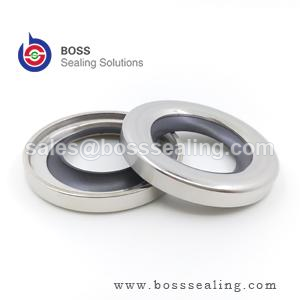
ما الذي تفعله الشفة فعلياً
لا يُحدث مانع التسرب الشعاعي ذو الشفة تلامساً بين المعدن والمطاط عبر سطح مبلل. ففي الظروف المناسبة تنزلق الشفة على غشاء زيت هيدروديناميكي بسماكة تتراوح بين 1 و3 ميكرومتر تقريباً، يتولّد عن دوران العمود ويستقر بفعل نمط النتوءات المجهرية لسطح العمود. ومهمة المانع هي الإبقاء على ذلك الغشاء بالسماكة الصحيحة: فإن كان الغشاء سميكاً جداً ضخّ الزيت خارجاً عبر الشفة؛ وإن انهار الغشاء أصبحت الشفة تعمل في تلامس حدّي عند كل بدء تشغيل، فتتآكل هي والعمود. ونطاق التلامس ضيق عمداً — بضعة أعشار المليمتر — بحيث يتركز الحمل الشعاعي في هلال مستقر على جانب الهواء.
وينتج عن ذلك نتيجتان تحكمان كل ما تبقّى في هذا المقال. أولاً، تتولد حرارة الاحتكاك في حجم صغير جداً: فسطح تلامس الشفة يعمل عادةً عند درجة حرارة تزيد بمقدار 15–40 °C عن السائل الأساسي، ما يعني أن حوض زيت عند 90 °C يطلب أصلاً من شفة NBR أن تصمد قرب حدّها المادي البالغ 100 °C. ثانياً، سطح العمود ليس متفرجاً سلبياً — فهو نصف النظام التريبي، وتحدد جودة تشطيبه وصلادته ونمط تجليخه ما إذا كان ذلك الغشاء الزيتي يمكن أن يوجد أصلاً.
مواد الشفة الأربع ونطاقاتها
مادة الشفة هي المرشّح الأول لأنها الأقل قابلية للتفاوض. وتتقارب بيانات المصنّعين المنشورة (بما في ذلك حدود الكتالوجات الواسعة الاستشهاد من Trelleborg وغيرها من منتجي الموانع — انظر نطاق موانع التسرب الدوارة من Trelleborg للحصول على أوراق بيانات العائلات الحالية) على النطاقات الواردة أدناه.
| مادة الشفة | درجة الحرارة المستمرة | أقصى سرعة محيطية | التوافق مع إضافات EP/AW | التشغيل الجاف |
|---|---|---|---|---|
| NBR (نتريل) | من −40 إلى +100 °م | ~12–14 م/ث | مقبول — ينتفخ مع الزيوت العدوانية من نوع GL-5 | ضعيف |
| ACM (بولي أكريلات) | −20 إلى +150 °C | ~18 م/ث | ممتاز — مادة إضافات EP | ضعيف |
| FKM (المطاط الفلوري) | −30 إلى +200 °C | ~35 م/ث | جيد — تحقّق مع الزيوت الاصطناعية الساخنة عالية الإضافات | مقبول |
| شفة PTFE | −60 إلى +250 °C | 40+ م/ث | خاملة عملياً | ممتاز |
اقرأ الجدول كسلّم استبعاد. فالزيت الأساسي عند 110 °C يستبعد NBR مهما كانت السرعة لطيفة. وعلبة التروس التي تعمل بزيت اصطناعي عالي الإضافات عند درجة حرارة تقصّر عمر NBR بشكل كبير — فـ ACM أو FKM يدوم عادةً ضعفين إلى ثلاثة أضعاف في نفس الهيكل، وهنا يغطي فرق سعر المادة نفسه عبر تجنّب التوقفات. توجد شفاه السيليكون لتطبيقات متخصصة وغذائية، لكن مقاومتها للتآكل الميكانيكي محدودة في الخدمة الدوارة المستمرة، لذا نتعامل معها كخيار متخصص لا كصف في الجدول.
السرعة هي أول حساب حقيقي
السرعة المحيطية، لا عدد الدورات في الدقيقة، هي التي تحدد بقاء الشفة. ويتم الحساب في سطر واحد:
v = π × d × n / 60,000 (م/ث)، حيث d قطر العمود بالمليمترات وn السرعة بالدورة في الدقيقة.
عمود بقطر 45 مم عند 1450 دورة/دقيقة يعطي v = 3.4 م/ث — مريح لـ NBR. ونفس العمود 45 مم على امتداد محرك عند 3600 دورة/دقيقة يعطي 8.5 م/ث — لا يزال داخل نطاق NBR، لكن حرارة الاحتكاك الآن تدفع سطح تلامس الشفة إلى 30 °C أو أكثر فوق الحوض، لذا لم يعد حوض عند 90 °C تطبيقاً لـ NBR. ومغزل بقطر 25 مم عند 12,000 دورة/دقيقة يعطي 15.7 م/ث — يتجاوز كل المطاطات عدا FKM، وهو حدّي حتى هناك؛ وهذا نطاق شفة PTFE.
القيم المرجعية القياسية، بما في ذلك متطلبات تشطيب السطح والصلادة المبنية حولها، موثقة في ISO 6194-1 وDIN 3760، ومُشار إليها مرجعياً في موارد هندسية عملية مثل The Engineering ToolBox. عندما تقع السرعة المحسوبة فوق 12–15 م/ث، انتقل إلى FKM؛ وفوق نحو 20 م/ث، حدّد شفة PTFE وجهّز السطح المقابل للعمود وفقاً لذلك.
تصاميم الشفة المطاطية: ما الذي يفعله الزنبرك وشفة الغبار
يظل مانع تسرب العمود الدوار المطاطي الكلاسيكي — هيكل معدني، وقطر خارجي مغطى بالمطاط، وزنبرك حزامي، وشفة مشذبة — الخيار الافتراضي للغالبية العظمى من الخدمات الدوارة تحت ضغط نحو 0.5 بار. وكل مكوّن يستحق موقعه. فالزنبرك الحزامي يحافظ على حمل شعاعي ثابت مع تآكل الشفة، أو مع أخذها تشوّهاً ضاغطاً من التقادم الحراري، أو مع تعويض سوء محاذاة بسيط للعمود؛ فالشفة التي “تبدو محكمة باليد” دون زنبرها تفقد ضغط التلامس في غضون أسابيع عند درجة الحرارة. ويُحكم القطر الخارجي المطاطي الإغلاق ضد تجويف الهيكل الذي لا يكون تشطيبه أملس كما يدّعي الرسم أبداً، ويستوعب فرق التمدد الحراري بين هيكل ألومنيوم وجلبة فولاذية.
يغطي ترقيتان في التصميم معظم ظروف الميدان. فشفة غبار ثانية متجهة للخارج تُبقي الرشّ والحبيبات ومياه الغسل بعيداً عن الشفة الأساسية — لكنها تضاعف الاحتكاك عند سطح التلامس، فتكلفك سعة سرعة؛ شغّل مانعاً بشفة غبار بفئة سرعة أقل بدرجة واحدة. وحيث يتجاوز الضغط نحو 0.5 بار — علب المضخات، وتجاويف المحركات، والمحاور الكوكبية — تنفتح الشفة القياسية أو تتآكل بالكامل. أما التصاميم المتوازنة الضغط بشفة معززة أقصر فتصمد لعدة بار؛ وما بعد ذلك فالإجابة الصحيحة هي مانع وجه ميكانيكي، لا شفة أكبر.
موانع الشفة PTFE: أين تستحق سعرها
تقلب شفاه PTFE منطق الإغلاق. فـ PTFE لا يمكن تشكيله بالقولبة كالمطاط، لذا تُشكَّل الشفة بالتصنيع الدقيق من قرص ملبّد أو مبثوق بالكبس وتُثبَّت ميكانيكياً في الهيكل. ولا يوجد زنبرك حزامي: تُشكَّل الشفة بهندسة تداخل تعتمد على ذاكرتها الانثنائية الخاصة — الشفة “محددة الذاكرة” — للحفاظ على التلامس. ونطاق التلامس أوسع بكثير من نطاق الشفة المطاطية، مع حمل نوعي أقل بكثير، وهو ما يسمح تحديداً بسرعات سطحية تتجاوز 35–40 م/ث ودرجات حرارة مستمرة حتى 250 °C مع تجاوزات قصيرة أعلى. والمادة خاملة عملياً تجاه المذيبات والأحماض والوقود ومعظم الوسائط الصناعية، وتتحمل بدء التشغيل الجاف الذي كان سيدمّر شفة NBR أو FKM في دقائق.
تصاميم شفاه PTFE عالية الأداء مجال هندسي ناضج وموثق — فالمتخصصون مثل Precision Polymer Engineering ينشرون النطاقات التي نلخصها هنا — وخطنا الخاص لموانع التسرب PTFE المنشّطة بالزنبرك يغطي المتغيرات الدوارة والتذبذبية حيث تحل شفة بوليمرية مع زنبرك معدني محل المطاط كلياً.
العمود الصادق: تكلف شفاه PTFE أضعاف نظيراتها المطاطية، وهي أقل تسامحاً مع انحراف العمود ونمط الخطوط وعيوب السطح لأن الشفة الصلبة لا يمكنها التكيّف، كما أن أضرار التركيب أقل قابلية للإصلاح — فشفة PTFE المثقوبة لا تتعافى كما يتعافى المطاط جزئياً. حدّد PTFE عندما تستبعد السرعة أو الحرارة أو الكيمياء المطاط فعلياً؛ أما الإفراط في تحديده لخدمة علبة تروس معتدلة عند 4 م/ث فلا يجلب شيئاً.
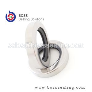
العمود نصف المانع
لا يصمد أي جدول مواد أمام سطح مقابل سيئ. والمتطلبات أدناه مستمدة من ممارسة ISO 6194 وهي القيم التي نضعها على رسومات الموردين.
| معامل العمود | شفة مطاطية | شفة PTFE | لماذا يهم ذلك |
|---|---|---|---|
| خشونة السطح Ra | 0.2–0.8 ميكرومتر | 0.1–0.4 ميكرومتر | Too rough abrades the lip; too smooth cannot hold the oil film |
| Counterface hardness | ≥ 45 HRC | ≥ 50 HRC | Below this, the lip machines a wear groove into the shaft |
| Grit-contaminated duty | 55+ HRC or hardened sleeve | Hardened sleeve preferred | Embedded grit turns the lip into a lapping tool |
| Plunge grinding | Required — no machine lead | Required, finer | A helical grinding pattern pumps oil out like an Archimedes screw |
| Runout and misalignment | Per ISO 6194 limits | Tighter — rigid lip will not conform | Excess runout breaks the meniscus on the air side each revolution |
Two shaft-side notes save real money. First, a shaft that has already run a seal for years usually carries a wear groove at the lip position; fitting the new seal on the old groove leaks from the first rotation. The cheapest correct fix is a thin-wall repair sleeve pressed over the shaft to a fresh diameter — a standard catalog item, not a machining job. Second, when a housing is reworked, check that the bore chamfer still leads the seal in square; a seal entered crooked damages its own lip before the machine ever runs.
Matching the Design Family to the Duty
| Duty | First choice | Alternative | التبرير |
|---|---|---|---|
| Clean industrial gearbox, oil < 90 °C, v < 8 m/s | NBR single lip | FKM for long service life | Cost-optimized; NBR fully inside its envelope |
| EP-additized synthetic oil, sump 100–140 °C | ACM | FKM | ACM exists for additive resistance; FKM wins on speed |
| v = 15–35 m/s, hot sump | FKM, hardened shaft | PTFE lip above 35 m/s | Friction heat, not fluid, is the failure driver |
| Aggressive media, dry start-ups, v > 35 m/s | شفة PTFE | Spring-energized PTFE | Only family with the temperature and chemical headroom |
| Wheel hubs, track drives, slurry, washdown | Cassette seal | Double lip + V-ring flinger | Contamination path must be a labyrinth, not a line |
| Pressure > 0.5 bar at the seal | Pressure-balanced lip design | Mechanical face seal | Standard lips blow open under sustained pressure |
Third-party catalogs such as Seal Sales و Darcoid are useful for cross-referencing common inch and metric sizes once the design family is decided — sizing is the easy part; the family choice above is what prevents the repeat leak.
Pressure, Vacuum and the Edges of the Lip Family
Pressure capability deserves its own paragraph because it is the most commonly misread column in seal catalogs. A conventional lip seal is a low-pressure device: the lip is designed to run against a flooded, essentially unpressurized sump, and sustained pressure above roughly 0.5 bar forces the lip against the shaft hard enough to tear the oil film and burn the contact band. Pressure-balanced lips — shorter, wider, backed by a full rubber face — push that boundary to around 5 bar in the better designs; beyond that, the conversation moves to mechanical face seals or packed glands, which distribute the load over faces designed for it. The corollary: if the pressure at the seal position is intermittent — pressure spikes from thermal expansion in a blocked-in line, for example — specify for the peak, not the average, because a lip fails in seconds at peak, not over months of average.
Vacuum runs the same physics in reverse and adds one demand: the seal must not admit air. For vacuum service, the lip faces the wrong direction or a double-lip arrangement seals both ways, and the shaft finish tightens toward the smooth end of the Ra band — but not past it, because a too-smooth shaft cannot hold the micro-oil film even at low speed, and the lip chatters. High-vacuum rotary duties are a PTFE-lip and spring-energized specialty for good reason; the elastomer families keep their properties down to rough vacuum but outgas and age differently at the deep end.
Speed at very small diameters and very large diameters also warps the standard table. Small shafts under 10 mm run light lips with little thermal mass — they overheat at speeds the table says are comfortable, because the published limits assume the heat sink of a mid-range diameter. Large shafts above 300 mm reverse the problem: peripheral speed is easy to satisfy, but runout, deflection and handling damage dominate, and the seal selection conversation becomes a housing-stiffness conversation. Neither extreme is exotic — mixer drives and calendar rolls live there — and both are the cases where a standard catalog pick most often needs an engineer’s override.
Reading a Failed Rotary Seal Before You Order the Replacement
The failed seal is a forensic report, and it is free. Read it before ordering, or the replacement inherits the same death. Lip hardened and cracked radially: thermal aging — the material ran past its temperature, usually because bulk sump temperature was mistaken for lip temperature; recheck the material row, not the brand. Lip worn on one side only, opposite side unworn: misalignment or bore-to-shaft misalignment beyond the runout limits — the seal was correct, the housing survey was not. Lip worn evenly but short life with a polished shaft wear track below the contact band: the shaft lost its hardness or the finish degraded through the wear groove; a repair sleeve is the fix, another seal is not. Swollen and soft lip: fluid incompatibility — check what actually went into the sump, because top-up fluids are the usual culprit when a seal that ran for years suddenly swells. Blistered or carbonized PTFE lip face: dry running or gross lubrication loss — investigate the oil level logic and the start-up procedure, because no material survives genuine dry rotation indefinitely. Extruded or rolled back on the pressure side: pressure exceeded the design — the duty changed even if the machine did not, and the answer is a pressure-balanced design or a mechanical seal.
Two inspection habits make this diagnosis reliable. Photograph the seal in the housing before removing it — the position of debris, the side of wear and the oil condition all change once the part comes out. And cut one worn lip in half: the contact band width and the subsurface cracking pattern distinguish heat aging from mechanical wear in ten seconds, which is the difference between ordering the same seal again and actually fixing the account.
Installation and the First Hour
Most rotary seals are killed during installation, not in service. Three disciplines prevent it. First, entry: the housing bore chamfer and the shaft end chamfer must lead the seal square; a seal entered cocked scrapes its own lip on the shaft keyway or thread, and the damage is invisible once the seal is home. Use an installation tool that pushes on the seal’s rigid case, never on the rubber face, and support the bore on the opposite side so the case cannot deform. Second, lubrication: wipe the lip and the shaft with the working fluid — never grease on a seal destined for oil service in a high-speed duty, because grease-lubricated start-ups run boundary contact far longer. Third, spring discipline: garter springs shift in transit; verify the spring is seated after handling, because a spring that pops out in the box is a seal that leaks in the first hour.
The first hour of running is part of the specification. Run the machine and check for weep at the shaft — a slight oil mist at the lip is normal during the first minutes as the seal laps itself in, but a drip within the first hour means the seal comes out and the diagnosis starts from the failure table above. Machines started on low oil level, cold oil or blocked breathers fail seals in that first hour at rates that no material selection can offset.
A Selection Workflow That Holds Up
Run the decision in this order and most seal problems never reach the machine. One: write down bulk fluid temperature, peripheral speed and media chemistry — the material table disqualifies before design matters. Two: check the pressure at the seal position; above ~0.5 bar, the standard lip family is out and the budget shifts. Three: classify the contamination — splash versus immersion versus slurry — and let that pick single lip, double lip or cassette. Four: audit the shaft with the table above, including a lead-pattern check on any reground surface. Five: only now open size catalogs. For non-standard bore or shaft dimensions, our rotary oil seal range covers the common ISO sizes and custom diameters, and our rubber seals line و high/low temperature seal range cover the elastomer variants in the material table. Where the envelope falls off every standard chart — combined speed, temperature and media — we design the lip to the duty through our customized products channel, which in practice is how most OEM spindle and mixer accounts end up specified.
الخلاصة
Select lip material from temperature and peripheral speed, select the design family from pressure and contamination, and then spend the remaining attention on the shaft — because the oil film the seal needs to survive exists only on a correctly finished, sufficiently hard, lead-free counterface. Get those three in that order and the seal becomes the boring, forgettable component it is supposed to be. Skip the shaft audit or let bulk sump temperature stand in for lip temperature, and no brand of seal will fix what the specification broke.
Lip Seals Matched to the Shaft
Rotary shaft seals are quoted against the shaft, not against a size list: PTFE lip seals for the speed and chemical envelope this article sets out, elastomer lip seals in NBR, FKM and silicone with the spring and dust lip the duty calls for, and cassette designs where contamination is the design case rather than an afterthought. Non-standard sizes are machined or molded to the housing and shaft dimensions you measure.
Before a lip material is proposed we ask for five numbers: shaft hardness, surface finish Ra, runout, speed at the lip, and the pressure the seal actually sees. Those decide whether a PTFE lip earns its price or an elastomer lip is simply correct. Where a shaft is marginal we say so, because no lip survives a counterface that was not finished for it.
Send the housing and shaft drawing, the speed and the medium to sales@bosssealing.com, and we will return the design family, compound and price with the shaft requirements written out. Replies usually within a day; the engineering review is free, and the نموذج الاتصال يصل إلى المكتب نفسه.