
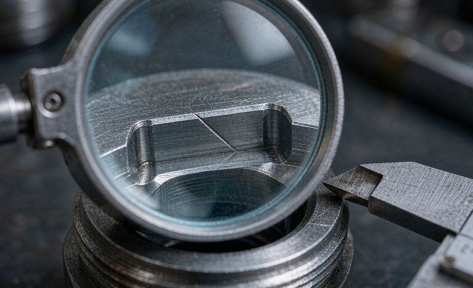
The most expensive seal replacement we hear about each month is not the one that leaks. It is the one where a technician used a hardened pick to lift a stubborn rod seal out of its groove, slipped, and gouged a 0.3 mm furrow across the groove flank. The new seal went in, the cylinder was reassembled, and it leaked from the first pressure cycle. The groove was scrap, and the repair became a new gland nut.
Replacing cylinder seals is mechanically simple and unforgiving. Almost every premature failure after a rebuild traces back to one of five things: a damaged groove, a cut lip, contamination left inside, a seal installed backwards, or a rod that was allowed to drag across the seal on assembly. None of them are detected by looking at the outside of a finished cylinder.
This is the procedure we recommend to service shops, in the order the work happens, with the checks that catch those five faults before the cylinder goes back on the machine.
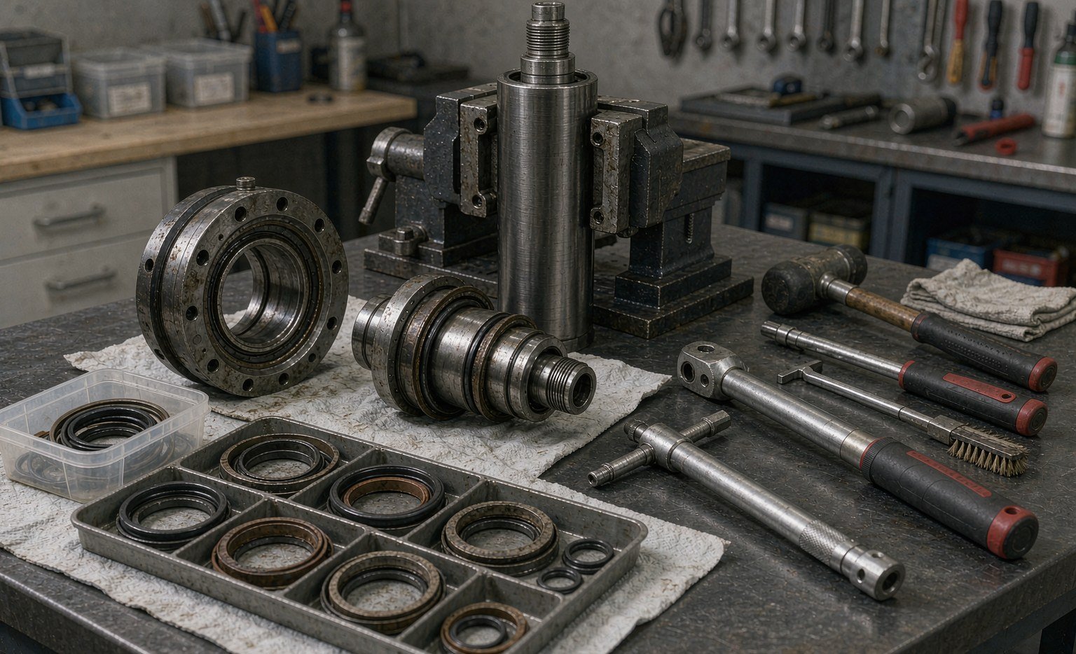
Before You Open It: Five Minutes of Diagnosis
A rebuild is the right answer to a leak only when the leak is the seal. Three quick checks separate the cases:
- Where does the oil appear? At the gland and only on the rod side points to the rod seal or wiper. Oil at a port or a weld points elsewhere. Oil that appears only under load points to a pressure-dependent seal fault rather than a static one.
- Does the cylinder drift? With the rod extended and the line blocked, mark the rod and time the movement. Drift with no external leak is piston seal bypass, which means the barrel comes apart whether or not the gland looks fine.
- What does the chrome look like? Run a fingernail along the rod through the wiper travel zone. Pits, score lines and flaking chrome will destroy a new seal in weeks. If the chrome is damaged, the job includes re-plating or rod replacement, not just seals.
Write the answers down with the machine hours. A cylinder that fails at 1,200 hours after a rebuild and one that fails at 12,000 hours are different problems, and the second one is usually just wear.
Document Before You Disassemble
Photos are the cheapest insurance in the job. Before anything moves, photograph the gland, the port positions, the rod end and the mounting. Mark the gland nut and the barrel with a paint line so the reassembly torque can be checked against the original position, and number the seal stack in the order it comes out.
The order matters more than most people expect. A buffer seal installed outboard of the rod seal, or a back-up ring on the wrong side of the pressure seal, produces a cylinder that holds pressure on the bench and fails within an hour in service. Lay the old parts out on a tray in the order removed, and photograph the tray.
Measure the housing before cleaning it. Groove width, radial depth and the bore at three points along the stroke take two minutes and tell you whether the replacement parts can be standard. A bore that is 0.05 mm oversize at the port end is a worn barrel, not a seal problem, and no seal will compensate for it.
Disassembly Without Heat and Without Force
Gland nuts and retaining rings come off with the correct tool: a pin spanner, a hook spanner, or the OEM socket. A pipe wrench on a gland nut leaves burrs that cut the new seal on reassembly, and it rounds the flats so the next technician has a worse day.
Heat is the other shortcut to avoid. Warming a gland to break a thread lock compound is acceptable at low temperature with a heat gun and a watchful eye, but a torch on an assembled gland will cook the seal inside and can distort the groove. If a nut will not move, use penetrating oil and time, or cut the nut off and replace it.
Never drive a screwdriver between the gland and the barrel to “persuade” it. That is how grooves get gouged and sealing faces get raised burrs. If the gland is stuck, a proper puller or a press with a soft pad is the answer.
Groove Inspection: Where Rebuilds Are Won
Once the parts are out and the housing is clean, inspect every sealing surface under good light with a magnifier. The defects below account for most of the repeat failures we investigate.
| Defect | How it happens | Consequence | Repair |
|---|---|---|---|
| Axial scratch across the groove flank | Pick or screwdriver used to lift the old seal | Leak path past the static face; new seal cut on installation | Polish out if under 0.05 mm deep, otherwise replace the part |
| Burr on the groove edge | Thread repair, wrench slip, machining chip left in place | Cuts the seal lip during assembly | Deburr with a fine stone, then verify Ra on the dynamic face |
| Rounded or battered groove corner | Repeated seal removal with sharp tools | Seal cannot seat; extrusion gap effectively larger | Replace gland nut or piston; do not build up with adhesive |
| Polished band with visible wear step | Bore wear at the stroke ends | Piston seal cannot follow; bypass and drift | Hone or replace barrel; check roundness |
| Corrosion pits in the groove | Water-contaminated fluid, long idle periods | Static leak and seal damage | Replace the component; pitting cannot be polished out reliably |
| Chrome flaking or pitting on the rod | Failed wiper, corrosive environment | Destroys every new rod seal | Re-plate and grind, or replace the rod |
The judgment call is depth. A scratch you can feel with a fingernail is usually too deep to polish out on a dynamic face, because removing enough material to blend it changes the groove dimension. On a static face, a shallow blend is acceptable if the surface still meets the Ra target. When in doubt, replace the part; a gland nut costs less than a second rebuild and the downtime around it.
Surface finish targets for the housing come from the same standards that define the groove. Dynamic faces at Ra ≤ 0.4 µm with a material ratio of 50 to 80 percent, static faces at Ra ≤ 1.6 µm, groove flanks at Ra ≤ 3.5 µm. A groove that measures 0.2 µm Ra but shows a torn, plucked surface will still wear a lip, because the plateau is too small to carry the load.
Cleanliness Is Part of the Repair, Not a Detail
A rebuild introduces contamination: airborne dust, lint from rags, metal from thread cleaning, old oil residue in the barrel. Every particle left inside goes through the new seal on the first stroke. This is why the flush and filter change at the end of the job are not optional, and why the bench itself matters.
| Item | Target | Why it matters here |
|---|---|---|
| Fluid cleanliness after repair | ISO 4406 18/16/13 or better | Standard hydraulic systems; particle counts above this shorten seal life |
| Fluid cleanliness, servo or proportional | ISO 4406 16/14/11 or better | Spool clearances of a few microns; silt jams valves and abrades seals |
| Bench surface | Clean, lint-free mat | Rags shed fibre that embeds in grease and seal lips |
| Cleaning agent | Purpose-made parts cleaner, fully dried | Solvent residue attacks elastomers and strips lubricant film |
| Barrel interior | Wiped with clean lint-free cloth, inspected by light | Honing residue and old oil varnish collect at the stroke ends |
Do not use compressed air from a general shop line to dry parts. A line without a dryer delivers water and oil aerosol straight into the groove. If air is the only option, use a filtered nozzle and follow with a lint-free wipe.
Fitting the Seal Without Cutting the Lip
Most installation damage happens in the last 10 mm of travel. The lip catches on a thread, a keyway, a snap-ring groove or a sharp chamfer, and a small piece of it folds back or tears away. The seal still looks installed. It will leak.
- Cover every interruption on the rod. Tape the thread, use a tapered installation sleeve, or wrap the keyway with shim stock. The sleeve should be smooth, deburred and lubricated with system fluid.
- Lubricate with the system fluid, not with grease or silicone spray. Grease can trap particles and is incompatible with some fluids; silicone contamination is a problem in paint and coating plants.
- Warm stiff seals. Polyurethane seats more easily at 50 to 60 °C in warm water. PTFE-faced seals are commonly warmed to 80 to 100 °C to soften them for stretching over a piston; use water or an oven, never a flame, and never heat beyond the material’s limit.
- Do not stretch beyond what the profile allows. A PTFE ring stretched over a piston must be resized with a sizing sleeve or left to recover at temperature. A PU U-cup stretched cold will stay distorted.
- Seat with a blunt tool, never a screwdriver. A plastic spatula or a brass drift with rounded edges will push a lip into a groove without cutting it.
- Confirm orientation before the gland goes on. The pressure side of a lip faces the pressure. On a rod seal, that is inboard. On a single-acting piston seal, it faces the chamber it seals.
If a lip folds during installation, take the seal out and fit a new one. A folded lip that is pushed back into place has a permanent set line and will leak at low pressure, which is exactly the condition that is hardest to diagnose on a machine.
Reassembly and Torque
Threads clean, dry or lubricated exactly as the OEM specifies — the two give very different clamp loads for the same torque figure. Use a calibrated wrench. Gland nut torque is not a place for estimation: too little and the static seal weeps, too much and the gland distorts the groove or yields the thread.
Guide the piston into the bore with a chamfer or a tapered ring, and support the rod so its weight does not hang on the new seal. On long rods, a sling at the centre of gravity is standard practice. A rod that enters the gland at an angle will shave the wiper and the rod seal on one side, and the damage is invisible from outside.
Check the piston wear rings before closing. A worn guide band lets the piston tilt, which opens the extrusion gap on one side and closes it on the other. The seal then fails by extrusion even though the clearance measured on the bench was in spec.
Commissioning: The Test That Finds the Fault
| Step | Method | Pass criterion |
|---|---|---|
| Air removal | Cycle the cylinder slowly at low pressure with the return line open to tank | Smooth motion, no judder or spongy response |
| Low-pressure cycles | 10 to 20 full strokes at 20 to 30 bar | No weeping at the gland, no squeal |
| Pressure hold | Hold rated pressure on the rod side with the piston port at tank, 5 minutes | No external leak, no measurable drift |
| Load hold | Hold a load at mid-stroke for 10 minutes, measure rod movement | Drift within the OEM allowance |
| Flush and filter | Run a low-pressure flush, then replace the return filter element | ISO 4406 sample at or below target |
| Temperature check | Run a duty cycle and measure gland temperature | Stable, no local hot spot at the gland |
A cylinder that passes the pressure hold but fails the load hold has a piston seal problem. One that passes both but weeps after an hour of running has a heat or finish problem. One that leaks immediately at low pressure usually has a folded or cut lip, or a seal installed backwards.
The Bottom Line
Seal replacement is a cleanliness and inspection job that happens to involve rubber parts. The parts are cheap, the labour is not, and the failure modes are almost all caused by the person doing the work rather than by the seal. Protect the groove, protect the lip, keep the inside clean, and test before the machine goes back into service.
Two habits separate shops with a low repeat rate from shops with a high one. They photograph the stack before disassembly, and they measure the housing instead of trusting the part number. Both take minutes, and both catch the errors that otherwise appear as a leak three weeks later.
We keep the consumables for this work together so a rebuild does not stall on a missing part: hydraulic seal kits and spare seals by cylinder series, rod seals and wiper seals in the same housing families, and back-up rings for the high-pressure jobs where the gap is tight. If a groove is already damaged, send the dimensions and a photo; matching a gland nut is faster than trying to polish out a scratch that is too deep.
For the design side of the same subject, Apple Rubber’s seal design guide covers groove geometry and installation chamfers, Balseal documents handling practice for precision seals, and Trelleborg’s hydraulic seal pages give profile-specific installation notes. For failure patterns, Marco Rubber’s failure analysis guide is a useful cross-check, and KASTAS publishes gap limits for high-pressure rod seals that explain why a groove that is 0.1 mm out of spec fails at 400 bar but holds at 200.