
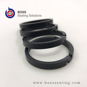
A backup ring is a flat, rigid ring that sits next to an elastomer seal on the low-pressure side and stops the seal from being forced into the gap between the metal parts. It does not seal on its own. It has no squeeze, no lip and no elastic memory. Its entire job is to close the extrusion gap so the O-ring behind it never has to flow into a space smaller than itself.
Most engineers first meet the part after a failure: an O-ring with one edge chewed off, a gland full of rubber crumbs, and a maintenance team replacing the same seal every few weeks. The fix is usually a ring that costs less than the O-ring it protects.
What Extrusion Actually Is
An elastomer under pressure behaves partly like a liquid. When 200 bar pushes an O-ring against the clearance between a piston and a bore, the material does not simply compress; it flows toward the path of least resistance, which is the gap. The gap on a new cylinder might be 0.15 mm. On a worn one it can reach 0.5 mm. At that size, an 80 °C NBR O-ring at 200 bar will push a visible tongue of rubber into the clearance within hours.
Once a tongue forms, the moving parts shear it off. The torn edge becomes a leak path, the leak raises local temperature, and the damage propagates around the circumference. The end state is a nibbled, flattened ring and a leak that no amount of tightening will stop.
A backup ring interrupts that sequence by occupying the gap with a material that will not flow at the operating temperature. It is a mechanical stop, not a seal.
Where the Ring Sits
Position is not negotiable: the backup ring goes on the side of the primary seal away from the pressure, facing the extrusion gap. In a rod gland pressurised from the bore side, the O-ring is loaded toward the gland outer edge and the backup ring sits between the O-ring and that edge.
In a double-acting cylinder the pressure alternates, so a single backup ring protects one direction only. Fit two, one on each face of the O-ring. Two rings also mean the groove must be wide enough: a standard O-ring groove sized for the O-ring alone will not accept a second ring without reducing squeeze to the point where the seal leaks at low pressure. Groove width, not ring thickness, is what constrains retrofit options.

The Five Standard Configurations
ISO 3601-4 groups anti-extrusion rings into five geometries. The differences are about how the ring gets onto the rod or into the groove without being cut, and how much continuous support it gives once installed.
| Type | Cut style | Installation | Where it is used |
|---|---|---|---|
| T1 | Spiral cut (continuous coil) | Wraps over a rod or into a groove without dismantling the assembly | Field repair, large diameters, retrofits on assembled cylinders |
| T2 | Angle cut (scarf) | Opens and snaps over the rod; ends overlap under pressure | General hydraulic service, both static and dynamic |
| T3 | Solid, uncut | Requires full access; slides over the end of the rod or piston | Highest extrusion resistance, aerospace and high-pressure static joints |
| T4 | Concave angle cut | Scarf cut with a profiled inner face | Precision glands where the ring must mate closely with the O-ring curve |
| T5 | Concave solid | Full access required; profiled inner face | High-pressure glands with tight axial space |
In practice, T2 is what most industrial cylinders use, T1 is what maintenance departments keep on the shelf for emergencies, and T3 is specified where the gland can be fully disassembled and the pressure justifies the assembly difficulty. A T3 ring forced over a rod with a screwdriver is a scrapped ring; the cut styles exist precisely to avoid that operation. Distributor catalogues such as Seal Sales backup rings show the same five families with stock sizes, which is a quick way to see what is available off the shelf before ordering a machined part.

Material Selection
The ring has to be harder than the O-ring at operating temperature but not so hard that it scores the bore. Three families cover almost every application.
| 材料 | Temperature | Pressure capability | Strengths | Limits |
|---|---|---|---|---|
| 純 PTFE | −200 to +260 °C | Good to ~250 bar with tight clearance | Lowest friction, wide chemical resistance, lowest cost | Cold flow under sustained load; deforms into large gaps |
| Filled PTFE (glass, carbon, bronze) | −200 to +260 °C | Good to ~400 bar | Higher compressive strength, better wear, less creep | Bronze filler can corrode in some media; slightly more abrasive |
| PEEK (unfilled or carbon/graphite filled) | −60 to +250 °C continuous | To 600 bar and above | Highest stiffness and creep resistance, holds large gaps | Higher cost, less conformable, needs good surface finish |
| Nylon / POM | −40 to +100 °C | To ~250 bar | Cheap, rigid, easy to machine | Swells in water and some glycols; limited chemical range |
| PU (high hardness) | −30 to +80 °C | To ~300 bar | Abrasion resistant, tolerant of poor surface finish | Poor at high temperature; not for aggressive fluids |
Two selection traps are worth naming. Virgin PTFE backup rings creep: under a sustained 300 bar static load at 80 °C, the ring slowly thins and the gap reopens. Filled PTFE or PEEK solves it, at a price. The other trap is nylon in water-based fluid. Nylon absorbs water, grows, and can seize in the groove, which is why water hydraulics and water-glycol systems use PTFE or PEEK instead.
The elastomer being protected matters as much as the ring. A 70 Shore A compound written to ASTM D2000 line notation is a different extrusion risk from a 90 Shore A compound in the same groove, and the ring thickness should follow the softer of the two.
When You Need One
There is no single pressure threshold in any standard, because extrusion depends on the combination of pressure, clearance, temperature and elastomer hardness. The workable decision rule uses all four.
| Condition | Recommendation |
|---|---|
| Below 100 bar, clearance within ISO 5597 limits, 70 Shore A O-ring | No ring needed |
| 100–160 bar, standard clearance | Optional; fit one on the pressure side as insurance on shock-loaded systems |
| 160–250 bar, or clearance above standard | One ring on the low-pressure side, filled PTFE |
| Above 250 bar | One ring standard; PEEK above 400 bar or where clearance exceeds 0.3 mm |
| Double-acting, above 160 bar | Two rings, one on each face of the O-ring |
| Any pressure with clearance above 0.4 mm | Fix the clearance first; a ring alone will not compensate for a worn bore |
The clearance half of that table matters more than the pressure half. A cylinder at 150 bar with a 0.5 mm gap extrudes faster than one at 300 bar with a 0.1 mm gap. If you are choosing between adding a backup ring and replacing a worn guide bushing, replace the bushing. Our guide elements exist for exactly that job: they hold the piston concentric so the clearance stays inside the range the seal was designed for.
Design Details That Decide Whether It Works
Groove width. A single backup ring needs roughly 1.2–1.5 mm of extra axial space, depending on ring thickness. Two rings need double that. If the groove was cut for an O-ring only, the options are a thinner ring, a machined ring that shares the O-ring’s space, or a different seal profile altogether. The housing conventions behind those numbers are the ones published by Hallite for hydraulic rod and piston seals, and they are the reference most European cylinder builders work from.
Edge radius. A sharp groove corner shaves a PTFE ring during installation and leaves debris in the gland. A 0.2–0.4 mm radius on the groove entry is normal practice and costs nothing at the machining stage.
表面光潔度。. The bore or rod under the ring should be no rougher than about Ra 0.4 µm for dynamic service. PTFE tolerates a rougher surface than PEEK; a PEEK ring running on a scored bore will wear the bore.
Thermal expansion. PTFE expands roughly ten times as much as steel per degree. Rings above 200 mm diameter need a diametral clearance allowance in the groove, or they will close up at 80 °C and grip the rod.
Installation Checks
Four checks catch nearly every backup ring installation error we see in returned parts:
- The ring is on the correct side. On a single-acting gland, the flat face of the ring faces the O-ring and the O-ring faces the pressure.
- The cut, if there is one, is offset from the O-ring’s own parting line and closed to a gap under 0.3 mm. A scarf joint that sits open at assembly stays open.
- The ring turns freely in the groove by hand. A ring that binds was machined to the wrong width or has absorbed fluid.
- The assembly was lubricated with system fluid, not grease that is incompatible with the elastomer. Lithium grease on an EPDM O-ring is a slow failure; on a PTFE ring it is harmless.
Adjacent Parts People Confuse With Backup Rings
Three parts get mixed up in requisitions, and ordering the wrong one wastes a cycle.
Wear rings (also called guide rings or guide bands) are radially loaded, carry side load, and are usually wider and thicker than a backup ring. They sit in their own groove, not next to the seal lip. Gaskets are flat static seals with no anti-extrusion function at all. Retaining rings are metal and hold parts in place, not fluid.
The confusion is understandable because a filled PTFE wear ring and a filled PTFE backup ring can come out of the same press with the same compound. They differ in section, tolerance and groove. A backup ring used as a wear ring will fail in shear; a wear ring used as a backup ring will not close the gap. Distributors such as Darcoid publish both families side by side, which makes the section differences easy to compare before ordering.
For the sealing side of the assembly, our gasket, washer and backup ring range covers the standard sections in PTFE, filled PTFE and PEEK, and the O-ring and X-ring range covers the elastomer these rings protect. Machined PEEK and PTFE parts outside standard sections come through our engineering plastics line, which is usually the faster route for retrofit rings on obsolete equipment.
Frequently Asked Questions
Can I fit a backup ring to an existing groove without machining?
Sometimes. If the groove already has 1.2 mm or more of axial space beyond the O-ring, a thin ring fits. If not, a machined ring with a reduced section can share the groove, but check that O-ring squeeze stays above about 8% before you commit. Below that, the assembly leaks at low pressure and the ring is irrelevant.
Does a backup ring increase friction?
It adds a small amount on the pressure side, and only while pressure is applied. In most cylinders the increase is not measurable against the rod seal’s own friction. In slow servo applications it matters, and a low-friction filled PTFE ring is the usual answer.
Why did my PTFE backup ring split after a few weeks?
Three causes, in order of frequency: the ring was installed on the wrong side and took the full extrusion load itself; the groove was too narrow, so the ring had nowhere to expand; or the ring was virgin PTFE in a continuous high-load static joint and cold-flowed until it cracked.
Is a backup ring the same as a T-seal?
No. A T-seal is a single part with an integral anti-extrusion profile, used where axial space is too tight for an O-ring plus two rings. It solves the same problem by a different route.
What is the cost difference between PTFE and PEEK rings?
For a 50 mm ring, expect PEEK at roughly two to four times the price of a filled PTFE ring. On a cylinder that runs 250 bar with a well-maintained bore, filled PTFE is the correct choice and PEEK is money spent on capability you will not use. Above 400 bar, or where clearance cannot be tightened, the PEEK ring is cheaper than the failures it prevents.