
A repair shop in Texas sent us a photograph last spring: a 90 Shore A polyurethane rod seal, fitted into a piston groove, extruded into the clearance gap after four hours on test. The seal was the right diameter, the right material and the right hardness. It sat in the wrong groove, facing the wrong way. The cylinder had been rebuilt by a contractor who ordered “a seal kit for a 100 mm bore” and installed whatever arrived in the box.
Rod seals and piston seals look similar in a catalog photo and behave nothing alike. One seals against a hard-chromed rod and has to leave a controlled oil film on the return stroke. The other separates two pressurized chambers inside the barrel and, on a double-acting cylinder, has to do it in both directions. The profile, the housing dimensions, the surface finish on the counterface and the failure modes all follow from that difference.
What follows is the selection order we use on the shop floor: pressure direction first, then counterface and gap, then profile, then material, then the details that belong on the drawing.
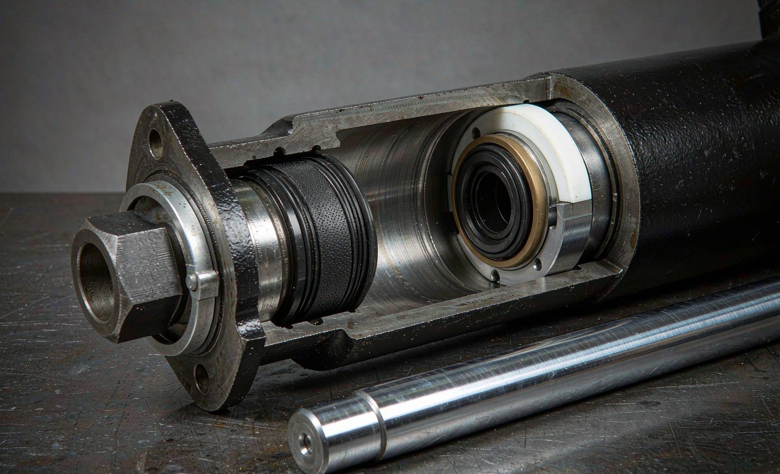
Start With the Pressure Side, Not the Profile
A single-acting lip seal has a pressure side and a low-pressure side, and the lip must face the pressure. On a rod seal, fluid enters the housing from the bore side, fills the space behind the U, and pushes the lips outward against the rod and inward against the groove. The harder the pressure, the tighter the seal. Turn the same seal around and the pressure now acts on the lip edge, lifting it off the rod. The cylinder will weep at 20 bar and fail visibly at 200.
This is not a subtle point in practice. On a U-cup or a V-set, the closed end of the profile goes toward the pressure. On a stepseal or a compact piston seal with an anti-extrusion ring, the ring goes on the low-pressure side, because that is the side the elastomer tries to flow toward. Get either wrong and the part is not “slightly worse” — it does not work at all.
A double-acting cylinder changes the problem. Both ports see full pressure at different times, so a piston seal has to seal in two directions. There are three ways to do it, and the choice drives cost and stack length:
- Two single-acting seals back to back. Simple, cheap, needs a longer piston and a drain or vent between them. Common on large bore mill cylinders.
- One double-acting compact seal. A filled PTFE or PU sealing ring with an elastomer energizer and one or two anti-extrusion rings, in a single housing. Short, low friction, tolerant of pressure reversal. The default on mobile hydraulics up to about 400 bar.
- A symmetric profile with two lips. A double U or a chevron stack with an adapter ring at each end. Used where the seal must also be field-repairable without a press.
The rod side is almost always single-acting. Fluid presses from the bore side only; the atmosphere is on the other side. That is why a rod seal can be a simple U-cup, and why a rod seal installed backwards is one of the most common rebuild errors we see in returned parts.
Two Counterfaces, Two Wear Mechanisms
The rod seal runs on a hard-chromed, ground and polished rod, typically 20 to 50 µm of chrome over an induction-hardened or case-hardened substrate. The surface is close to mirror finish, the tolerance is tight, and the seal sees the same narrow band of chrome several million times. Wear on that interface is dominated by the oil film: too little and the lip runs dry and hardens; too much and the cylinder leaves a film on the rod that attracts dust.
The piston seal runs on a honed bore. The bore carries a cross-hatch from honing, holds oil in the valleys, and is far larger in circumference, so a single piston seal sweeps several times the area of a rod seal per stroke. It also sits closer to the contamination that enters through the breather and the return line. A particle embedded in the bore scores a piston seal along its whole travel; the same particle on a rod is wiped off at the gland before it reaches the seal.
Those two facts explain most of the material split in the catalogs. Rod seals lean on polyurethane for abrasion resistance and on PTFE compounds for low friction and high speed. Piston seals lean on fabric-reinforced NBR, filled PTFE and PU, with the choice driven by pressure and by how much side load the piston carries.
| Characteristic | Rod seal | Piston seal |
|---|---|---|
| Pressure direction | One side only, from the bore | One side on a single-acting cylinder, both sides on a double-acting one |
| Counterface | Hard-chromed rod, Ra 0.1–0.4 µm | Honed bore, Ra 0.2–0.4 µm with cross-hatch |
| Leak consequence | Visible external leak, oil on the rod, environmental and safety issue | Internal bypass, no visible leak, drift and heat |
| Typical profiles | U-cup, stepseal, VARISEAL, buffer seal, chevron set | Compact seal, double U, fabric V-set, PTFE stepseal with two anti-extrusion rings |
| Housing standard | ISO 5597 rod series, ISO 7425-2 for plastic-faced | ISO 5597 piston series, ISO 7425-1 for plastic-faced |
| Gap control | Gap at the gland bore to rod clearance | Gap at the piston OD to bore clearance |
| Service access | Gland nut or retaining ring, no barrel disassembly on many designs | Requires opening the cylinder and removing the piston |
| Common failure | Lip hardening, chrome scoring from a failed wiper, extrusion at high pressure | Bypass from a worn dynamic edge, extrusion into the bore gap, spiral failure from side load |
The Standards That Decide the Groove
Most arguments about seal interchangeability are really arguments about housings. Two seals with the same 100 mm bore and the same 12 mm height are not interchangeable if one is designed for a 7.5 mm radial depth and the other for 8.0 mm. The axial and radial dimensions come from the housing standard, not from the seal drawing.
ISO 5597:2018 is the reference for single-acting rod and piston seal housings on reciprocating cylinders. It covers cylinders from 16 mm to 500 mm bore and rods from 6 mm to 450 mm. It also defines a second, compact range for cylinders built to ISO 6020-2 at 160 bar (16 MPa), where the bore runs 25 mm to 200 mm and the rod 12 mm to 140 mm. That compact range uses smaller seal sections and, as a direct consequence, tighter tolerances on the bore and rod — the same nominal pressure in less radial space.
The same standard carries the surface requirements that get argued about at goods-in: dynamic sealing faces at Ra ≤ 0.4 µm, static sealing faces at Ra ≤ 1.6 µm, groove flanks at Ra ≤ 3.5 µm, and a material ratio Rmr of 50 to 80 percent measured to ISO 4287. The Rmr clause is the one drawing reviewers skip. A bore can hit 0.3 µm Ra and still fail a seal if the plateau is too small, because the load is carried on a few peaks instead of a broad plateau.
- ISO 5597:2018 — housings for single-acting piston and rod seals, 16–500 mm bore and 6–450 mm rod, plus the compact range built around ISO 6020-2. Fixes groove width, radial depth, tolerances and surface finish values.
- ISO 7425-1 and -2 — housings for elastomer-energized, plastic-faced seals, piston in Part 1 and rod in Part 2. Fixes the groove geometry for PTFE-faced seals, including the space reserved for anti-extrusion elements.
- ISO 6195:2021 — wiper-ring housings from 4 mm to 450 mm rod diameter, with housing types A to E. Fixes wiper groove depth, width, chamfer and finish.
- ISO 6020-1 and -2 — cylinder envelope for the 160 bar and 250 bar series. The compact seal housings are drawn around these bore and rod envelopes, which is why the same pressure in a smaller section demands tighter tolerances.
Where a customer drawing cites only a seal part number and no housing standard, we ask for the groove dimensions before quoting. Nine times out of ten the drawing is fine and the part number is a cross-reference to a competitor’s catalog that has been copied three times. The tenth time, the radial depth is 0.5 mm off and no standard seal will hold.
Extrusion: The Number That Limits Everything
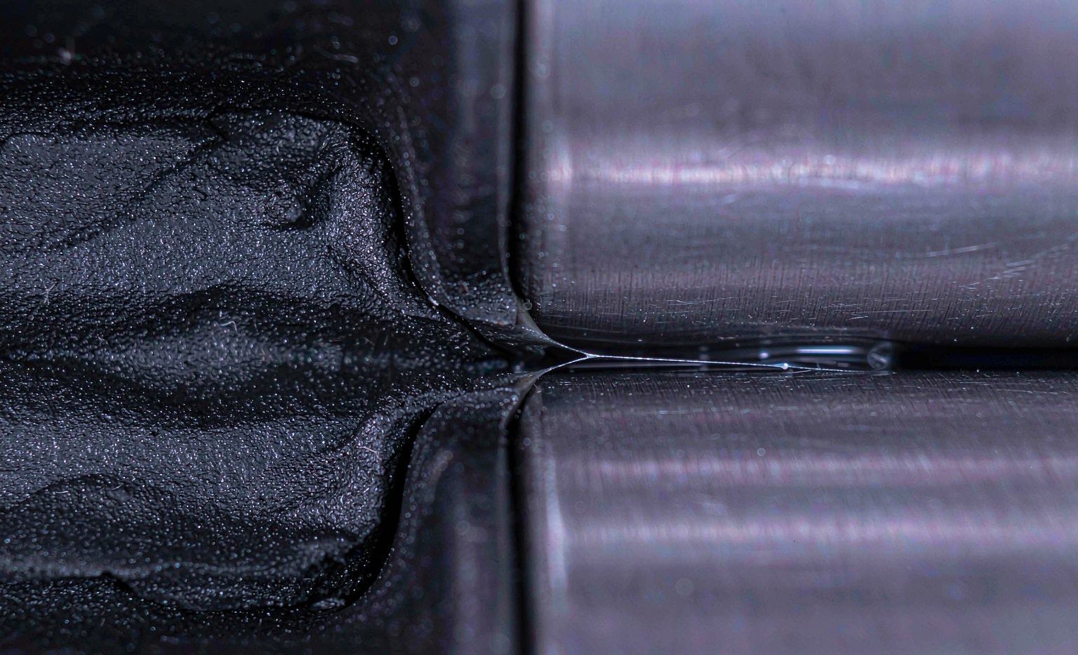
Every pressure-energized seal is pushed toward the low-pressure side. If the gap it faces is small enough, the elastomer or PTFE is restrained by the groove flank and the metal land; if it is not, the material creeps into the gap, gets sheared off on the pressure cycle, and the seal loses section. This is the single most common high-pressure failure, and it is a clearance problem before it is a material problem.
The allowable gap falls quickly with pressure. Published figures for a polyurethane buffer seal with an integrated polyamide anti-extrusion ring, referenced to 80 °C, are 0.8 mm at 160 bar, 0.55 mm at 250 bar, 0.35 mm at 400 bar and 0.15 mm at 690 bar. A PTFE-faced compact piston seal with two thermoplastic back-up rings is listed at 0.8 mm at 160 bar and 0.25 mm at 600 bar for sections up to 7.5 mm. Both sets of numbers come from the same physical rule: as pressure rises, the permitted diametral clearance shrinks, and the seal construction has to change with it.
| System pressure | Max extrusion gap, PU seal with anti-extrusion ring | Max gap, PTFE compact seal, section ≤ 7.5 mm | Practical hardware change |
|---|---|---|---|
| 160 bar (16 MPa) | 0.80 mm | 0.80 mm | Standard clearance, single seal |
| 250 bar (25 MPa) | 0.55 mm | 0.70 mm | Tighter bore fit, check piston wear ring |
| 320 bar (32 MPa) | — | 0.50 mm | Add or upgrade back-up ring |
| 400 bar (40 MPa) | 0.35 mm | 0.40 mm | Two back-up rings, hardened groove flanks |
| 600 bar (60 MPa) | — | 0.25 mm | Composite seal, minimum clearance, guided piston |
Values are published catalogue limits for specific seal families at a reference temperature; they are not a general rule for any seal. Gap limits tighten as temperature rises because the elastomer softens. Verify against the data sheet of the seal you are actually buying.
Two hardware details decide whether you stay inside those limits. The first is piston and rod guidance. A piston that relies on the seal to centre it will tilt under side load, open the gap on one side and close it on the other; a wear ring or guide band costs a few dollars and removes the problem. The second is groove flank hardness and edge break. A soft flank yields under the same load the seal sees, which effectively increases the gap. We specify flanks at 45 HRC or better on cylinders above 250 bar.
The Rod Side Is a Stack, Not a Seal
Most rod assemblies carry three components, and the order matters. From the atmosphere inward: wiper, rod seal, buffer seal. On mining and construction cylinders there is often a fourth element, a wear ring or a secondary seal in a separate housing.
The wiper sits at the outer face and scrapes mud, dust and ice off the chrome before the rod re-enters the gland. It is not a pressure seal. Its lip runs dry by design, which is why wiper materials are chosen for dry abrasion rather than for fluid compatibility.
The rod seal does the pressure work. It has to hold static pressure without weeping and dynamic pressure without generating so much friction that the cylinder judders at low speed. A U-cup in PU handles this up to roughly 400 bar at moderate speed; a PTFE-faced stepseal takes over when friction, speed or temperature move outside the PU window.
The buffer seal, where fitted, absorbs the pressure spikes that occur when a cylinder bottoms out or a valving event sends a shock down the line. It protects the rod seal from the peak and vents the trapped oil back to the bore through small grooves or holes. On a cylinder that runs at 250 bar but sees 450 bar spikes, the buffer is what keeps the rod seal alive.
The stack also defines where leakage goes. A failed wiper produces a scored rod, which destroys the rod seal within weeks. A failed rod seal produces an external leak that is easy to see. A failed buffer produces a rod seal that keeps failing for no apparent reason, because the pressure spike it was meant to absorb now arrives at the lip.
Piston Options and What Each One Costs You
The piston side has more variety because it has to handle pressure reversal, side load and, on large cylinders, a long sealing circumference.
Compact PTFE seals are the default for mobile hydraulic pistons up to 400 bar. Low friction, no stick-slip, short housing, tolerant of pressure reversal. They cost more than a rubber U-cup and need a well-guided piston, because the PTFE ring has almost no ability to conform to a tilted bore.
Polyurethane U-cups, single or double, are cheap, forgiving and available everywhere. They handle 300 to 400 bar in clean fluid, tolerate modest misalignment, and give good abrasion resistance. They do not tolerate fast cycling at high pressure as well as PTFE, and they generate more friction.
Fabric-reinforced NBR V-sets appear on large bore, low-speed cylinders — presses, mill duty, ship steering gear. The stack is tall, the adjustment is mechanical, and the seal can be re-tightened in service. It is old technology that still works where space is not the constraint.
Two single-acting seals remain the pragmatic answer above 500 mm bore, where a compact seal in one housing becomes expensive and hard to install without damage.
Failure Signatures That Point to the Right Seal
Diagnosis is faster if you treat the leak pattern as data. The table below is the one we use when a customer sends a photo and a complaint.
| Signature | Most likely cause | What to check before replacing |
|---|---|---|
| External leak that stops when the rod is fully retracted | Rod seal lip worn or hardened | Rod finish, wiper condition, fluid temperature history |
| External leak that continues at rest | Rod seal extruded or cut at installation | Gland chamfer, gap at the housing, seal orientation |
| No external leak but the cylinder drifts under load | Piston seal bypass | Bore roundness and taper, piston clearance, seal hardness |
| Rod seal fails every few weeks | Wiper failed, chrome scored | Chrome pits and score depth, wiper lip, environment |
| Seal torn on one side, spiral marks | Piston tilt or side load | Wear ring clearance, rod alignment, mounting stiffness |
| Seal flattened, hard, cracked at the lip | Heat or incompatible fluid | Oil temperature at the cylinder, fluid specification, cooler performance |
| Seal nibbled on the low-pressure edge | Extrusion from excess gap | Diametral clearance, back-up ring presence, pressure peaks |
Note how many of these are not seal problems. Three of the seven are installation or hardware faults, and one is a fluid problem. Replacing the seal without addressing the cause buys a few weeks.
A Selection Sequence in Seven Steps
- Fix the pressure direction. Single-acting or double-acting, and is there a pressure spike above the nominal rating. A cylinder rated 250 bar that sees 400 bar at end of stroke is a 400 bar application.
- Measure the housing, not the old seal. Groove width, radial depth, bore and rod diameter, and the corner radii. Old seals are swollen, worn or simply wrong.
- Calculate the gap at operating temperature. Take the worst-case clearance from the tolerance stack, not the nominal. Compare it with the gap limit for the pressure and temperature on the data sheet.
- Choose the counterface finish. Dynamic faces at Ra ≤ 0.4 µm with Rmr 50–80 percent; check the rod chrome for pits, not just roughness.
- Pick the profile family. PU U-cup for cost and tolerance of misalignment; PTFE-faced for friction, speed and temperature; fabric V-set for large bore and low speed.
- Pick the compound. Fluid compatibility first, temperature second, hardness third. A 95 Shore A PU is not automatically better than a 93; it conforms less and is more notch-sensitive.
- Specify the hardware that protects the seal. Guide rings, buffer seal, wiper, chamfer, and a groove flank hard enough not to yield.
What Belongs on the Drawing and the Purchase Order
A seal order that says “rod seal 100 x 115 x 12, PU” is a guess. The same order with six more lines removes most of the risk:
- Housing standard and series, for example ISO 5597 rod series or ISO 7425-2.
- Nominal pressure and peak pressure, with the peak duration.
- Fluid type, including any water-glycol or biodegradable ester, and the operating temperature range.
- Rod or bore surface finish and hardness, with the Rmr value if the drawing already specifies it.
- Speed and duty cycle — continuous reciprocation and a few strokes a day are different applications for the same seal.
- Whether a buffer seal and wiper are part of the assembly, and their part numbers.
For a distributor or a shop rebuilding mixed fleets, the practical version of this is a cross-reference table that maps the OEM part number to the housing dimensions, not just to a competitor’s seal number. We publish ours with the groove dimensions attached, because that is the data that survives a supplier change. The hydraulic rod seal range and the piston seal range are grouped by housing series for exactly that reason, and the combined rod and piston seal pages list the groove data alongside the profile.
Two external references are worth keeping on the bench. Trelleborg publishes hydraulic seal data with gap limits by profile, and Apple Rubber’s seal design guide covers gland geometry in plain language. For a second opinion on gland design from a distributor’s side, Marco Rubber keeps a useful reference page, and ERIKS documents the same rules for the European market. Hallite’s hydraulic seal pages are a good cross-check on housing dimensions when an OEM drawing is missing.
Key Takeaways
- Pressure direction comes first. A single-acting lip seal installed backwards will hold low pressure and fail at high pressure. On a double-acting piston, use two seals back to back or a genuinely double-acting profile.
- Housings, not part numbers, define interchangeability. ISO 5597:2018 sets the groove dimensions for 16–500 mm bores and 6–450 mm rods; ISO 7425-1 and -2 cover plastic-faced seals; ISO 6195:2021 covers wipers from 4 mm to 450 mm rod.
- Extrusion is a clearance calculation. Allowable gap falls from about 0.8 mm at 160 bar to 0.15–0.35 mm at 400–690 bar, depending on the seal construction. Adding a back-up ring is cheaper than adding hardness.
- Surface finish needs Rmr, not just Ra. Dynamic faces at Ra ≤ 0.4 µm with a 50–80 percent material ratio is the ISO 5597 target; a mirror finish with a poor plateau still wears seals.
- Most rod seal failures start elsewhere. A failed wiper scores the chrome, a missing buffer seal lets spikes through, and a tilted piston opens the gap. Fix the cause or the new seal will fail on the same schedule.
- Order by dimensions and duty. Pressure, peak pressure, fluid, temperature range, speed, finish and housing standard on the PO. It costs nothing and removes the most common reason a correct seal fails.
If you are rebuilding a mixed fleet and cannot identify a housing, send the groove dimensions rather than the old seal. We will match the profile to the housing and tell you if the clearance is outside the limit for your pressure. That conversation takes one email and saves the second rebuild.