
Two hydraulic cylinders left the same shop in the same week. Both had 63 mm bores, both were honed to a mirror, both were assembled with 70 Shore A NBR rod seals from the same box. One ran 14 months and was still dry at the wiper. The other leaked at the rod seal within six weeks, and when we cut the cylinder open the bore had a finish that looked perfect and a lay pattern that ran straight down the stroke.
Groove and bore finish is the most under-specified dimension in seal design and the one that decides life most often. It is also the one most easily faked by a number: Ra can be measured on a bad surface and still read 0.4 µm.

Ra Is a Number, Not a Specification
Ra is the arithmetic mean of profile deviations over a sampling length. It averages peaks and valleys into a single figure, which means a surface with 2 µm peaks and 2 µm valleys scores the same as one that is flat with occasional 4 µm scratches. A seal does not care about the average. It cares about whether the peaks cut it and whether the valleys form a continuous path from the oil side to the air side.
Three parameters beyond Ra decide which of those happens:
- Rz (maximum height of profile, averaged over five sampling lengths) tells you the peak-to-valley depth. A surface at Ra 0.4 µm with Rz 4 µm has isolated deep valleys — a leak path. The same Ra with Rz 1.6 µm is uniform.
- Rmr (material ratio at a given cut depth) tells you how much of the surface is bearing load. A plateau-honed bore can carry 60-70% material at the depth where the seal contacts; a sharply turned bore carries 20-30%.
- Lay tells you the direction of the marks. This is not a number on a report and it decides more failures than either roughness parameter.
ISO 3601-2 treats finish as part of the gland specification rather than a note, and the 2025 revision pushes users toward controlling material ratio alongside Ra. That is the right direction: a drawing that says “Ra 0.4” and nothing else lets a shop deliver a screw thread.
The Numbers, by Application
The table below consolidates the values used by the major seal houses. They are targets for the sealing face, not for the whole part.
| Sealing face | Ra target | Rz / Rmax | Typical process | Notes |
|---|---|---|---|---|
| Static, non-pulsating (flange, cover) | ≤ 1.6 µm | ≤ 6.3 µm | Fine milling or turning | 32 µin. The default for most gaskets and face seals |
| Static, pulsating or gas service | ≤ 0.8 µm | ≤ 3.2 µm | Grinding or fine boring | Gas and low-viscosity fluids find leak paths that oil does not |
| Groove bottom and side walls | 1.6-3.2 µm | ≤ 6.3-12.5 µm | Turning or boring | Loose is fine. Rough side walls abrade the ring on assembly |
| Reciprocating dynamic (rod, bore) | ≤ 0.4 µm | ≤ 1.6 µm | Honing, grinding | 16 µin. The single most important number in a hydraulic gland |
| Dynamic groove bottom | ≤ 1.6 µm | ≤ 6.3 µm | Turning | Prevents extrusion damage and seal roll during installation |
| Rotary, high pressure | 0.2-0.4 µm | ≤ 1.6 µm | Grinding, superfinishing | Lay must be circumferential, never axial |
| Vacuum | ≤ 0.4 µm | ≤ 1.6 µm | Honing or lapping | Leak direction is inward; surface defects matter more than pressure |
One floor value belongs under that table: do not go below roughly Ra 0.1-0.15 µm on a dynamic face. A polished-to-mirror bore cannot hold an oil film, and the seal runs on boundary lubrication from the first stroke. Wear accelerates, friction rises, and the failure looks like a material problem when it is a finishing problem.
Two Failure Modes, One Number
The leak path
A static seal at 1 MPa does not need much of a channel. Consider a groove face at Ra 2.5 µm with a lay that runs radially outward from the bore to atmosphere. Under compression, the rubber fills most of the valleys, but where two adjacent scratches intersect and both reach the edge, you have a continuous capillary. At low pressure, surface tension holds it; at 0.05 MPa of thermal cycling and a fluid with a surfactant in it, it weeps.
This is why the fix for a weeping flange gasket is often not a harder gasket or more bolt torque, but a change from a turned face to a ground face. Torque closes gaps in the rubber, not channels in the steel.
The dry stroke
The opposite failure. A rod finished to Ra 0.05 µm looks like a bearing race and seals nothing well. The rod seal lip needs a film of oil roughly 1-3 µm thick to stay lubricated, and that film is carried in the surface texture. Remove the texture and the lip runs dry, glazes, hardens, and eventually takes a set that leaves it unable to follow the rod. Oil consumption drops, which looks like an improvement, until the seal starts passing with the machine at temperature.
We see this most on cylinders that were reworked by a shop with a polishing lathe and no seal specification. The bore is beautiful. The seal fails in eight weeks and the report says “seal material failure.”
How the Finish Is Produced, and Why It Matters
| Process | Ra achieved | Lay | Bearing ratio | Best for |
|---|---|---|---|---|
| Turning (finish pass) | 0.8-3.2 µm | Circumferential or helical | Low, 20-35% | Groove bottoms, static faces, non-sealing surfaces |
| Cylindrical grinding | 0.1-0.8 µm | Circumferential, fine | Medium, 40-55% | Rod surfaces, rotary shafts |
| Honing | 0.2-0.8 µm | Cross-hatch, 30-60° included | High, 50-70% | Cylinder bores, anything reciprocating |
| Roller burnishing | 0.05-0.4 µm | Circumferential, smeared | Very high, 70-85% | Static faces where flatness matters |
| Ballizing | 0.1-0.4 µm | Circumferential | High | Small bores, through holes |
| EDM | 0.4-3.2 µm | Random, recast layer | 낮음 | Not a sealing face without post-finishing |
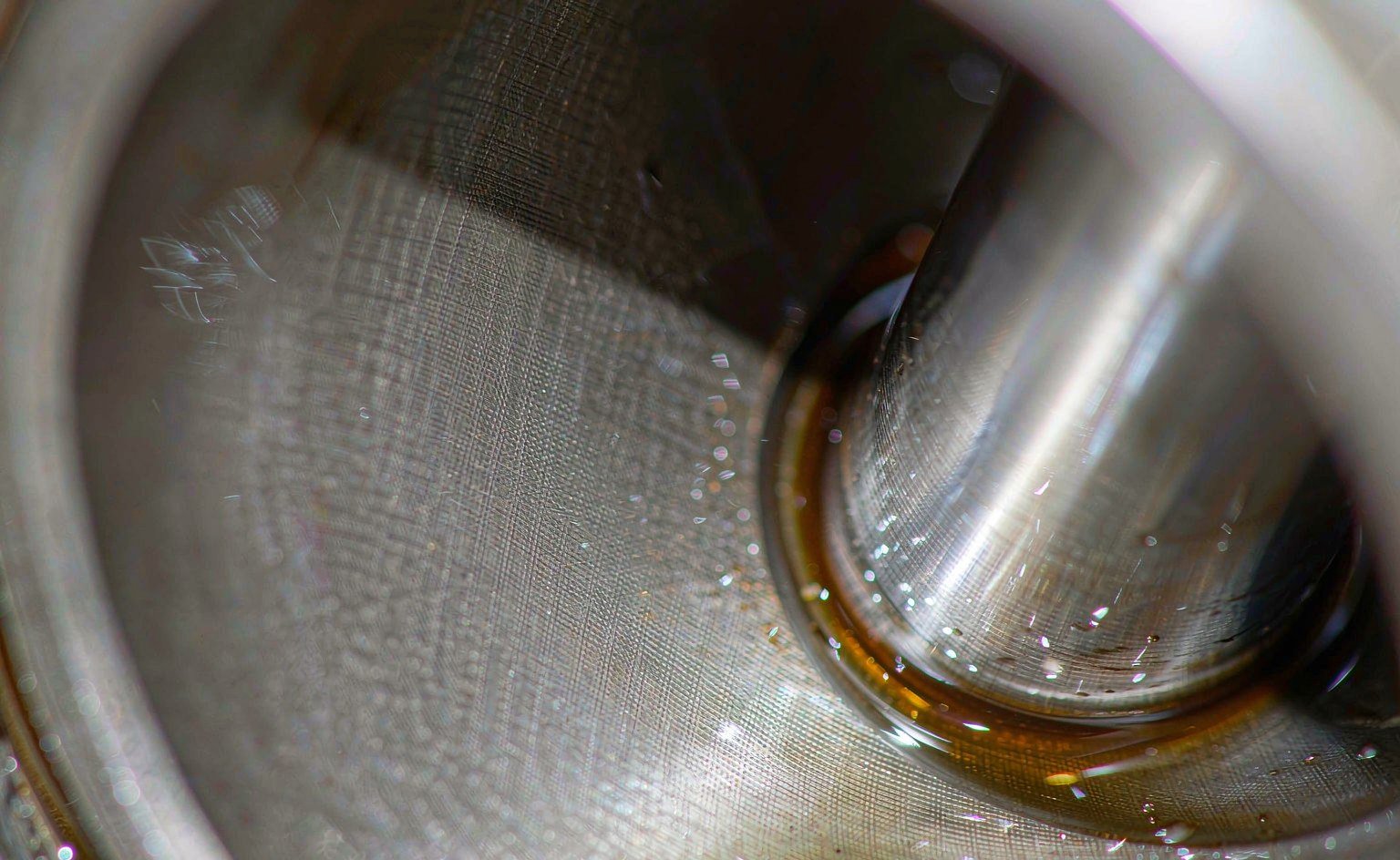
Honing is the right process for a reciprocating bore for one reason: the cross-hatch. The included angle between the two sets of scratches, usually 30-60°, keeps oil in the bore during the stroke and releases it on the return. A single-direction hone, or a grind, produces scratches that run with the stroke and act as a pump. Both can read Ra 0.4 µm. Only one holds oil.
Roller burnishing produces the finest Ra of the list and is the process most often over-applied to dynamic faces. It smears peaks into valleys rather than cutting them away, which raises the bearing ratio and closes the oil pockets. On a static face that is exactly what you want. On a rod it produces a surface that measures beautifully and lubricates poorly.
What Actually Gets Measured in the Shop
Most incoming inspection of a seal gland is a visual check and a caliper. That catches the wrong things and misses the right ones. If finish matters on the drawing, four details decide whether the measurement means anything:
- Cutoff length. A 0.8 mm cutoff on a turned surface with a 0.4 mm feed rate returns a different Ra than a 2.5 mm cutoff on the same surface. Compare only traces taken with the same cutoff, and put the cutoff on the drawing next to the Ra.
- Stylus and skid. A 2 µm stylus cannot resolve a valley narrower than its tip. A skid that bridges a 3 mm bore measures the average of the bridge, not the surface.
- Position and count. Three traces at 120° around a bore, plus one along the axis. A single axial trace on a honed bore will read the cross-hatch; a single circumferential trace will read a different surface entirely.
- Cleanliness and temperature. Oil film on the surface damps the stylus and reads smoother. Solvent-wipe and dry before measuring, and measure at shop temperature after the part has stabilized.
The practical shortcut for a production floor without a profilometer is a comparator plate plus a cast. A replica cast of the bore, sectioned and compared against a known-good sample, catches lay defects that a handheld gauge never will. It costs a fraction of a stylus instrument and it is used more often.
The Cost of Over-Specifying
Finish is one of the few specifications where tighter is not free and not always better. Moving a face from Ra 3.2 µm to 1.6 µm adds roughly 30-50% to the machining cost of that face. Moving from 1.6 µm to 0.8 µm can double it, because it usually changes the process from turning to grinding and adds a second setup.
Blanket notes are where the money goes. A drawing that says “all surfaces Ra 0.4” on a 200 mm manifold pays grinding cost on bolt faces, mounting pads and clearance bores that never see a seal. The correct note specifies a general tolerance — Ra 3.2 µm unless otherwise stated — and calls the tight value on the sealing faces only. One 10 × 10 mm sealing land does not require the whole flange to be ground.
Why This Matters More in Repair Than in New Build
A new cylinder arrives with a bore finished to the OEM’s process, which is usually correct because it was validated over thousands of units. A repaired cylinder is finished by whoever has the machine available. Re-boring oversize and fitting a thinner seal, welding and re-machining a rod, or honing out a score mark all reset the surface, and none of those operations automatically restore the lay or the oil retention.
When we supply seals into repair shops, we ask for the bore finish and the rod finish before recommending a profile. A rod seal with a sharp lip will tolerate a rougher rod than a lip with a wide contact band. A wiper with a hard scraper edge will survive a surface that would destroy a soft one. The finish and the profile are one decision, and shops that treat them as two end up changing seals instead of specifications.
Field Checklist Before You Sign Off a Gland
- Ra and Rz both on the drawing, with cutoff length and the faces named. Ra alone is not a specification.
- Lay direction stated. Circumferential for rotary, cross-hatch for reciprocating bores, random or radial-free for static faces.
- No floor below 0.1-0.15 µm on dynamic faces. If a shop delivers a mirror, ask what oil film is supposed to survive on it.
- Material ratio checked once per batch on the sealing face if the process is honing or burnishing.
- Edge break specified: 15-20° lead-in chamfer, deburred, with the chamfer surface no rougher than the bore.
- Porosity and plating checked on hard-chrome rod surfaces. Chrome nodules and pits are leak paths that no Ra value describes.
- One known-good sample kept as a physical reference, cast or sectioned, so the next argument is settled in thirty seconds.
Our O-링 및 X-링 제품군 is specified against these values in the gland dimensions we publish, and the same logic applies to rod seal profiles, where lip geometry and rod finish have to be matched rather than specified independently. Where a 백업 링 sits against a groove side wall, that wall’s finish controls how the ring wears, not just how the O-ring seals.
For reference values from a seal manufacturer’s own design guide, Trelleborg’s sealing solutions library 와 Hallite’s hydraulic seal documentation both publish finish tables by duty. Balseal’s material pages are useful when the question is whether a compound change can compensate for a finish you cannot fix. Distributor notes on field failures at Seal Sales 와 Darcoid cover the same ground from the counter side, where the finish is usually unknown and the seal gets blamed anyway.
Related: what a backup ring does and how extrusion gap and surface finish interact at pressure.