
A 32 mm bore pneumatic cylinder supplied at 1 bar produces about 80 N of theoretical thrust. Subtract rod and guide friction, subtract the load, subtract the pressure lost through a 3-metre tube and two fittings, and the margin left to move the piston is often under 25 N. Now put a seal in that gland with 15 N of breakaway friction and the cylinder stops moving reliably — not because it is undersized, but because the seal was chosen from a catalogue page that listed a friction coefficient with no test conditions attached.
Low-friction pneumatic sealing is a force-budget problem before it is a material problem. The specification that works states the breakaway force the cylinder can afford, the speed and pressure at which it must be measured, and the leakage that is not acceptable. Everything else — profile, compound, finish — follows from those three numbers.
Start With the Force Budget
Take the smallest pressure at which the cylinder must start moving, not the nominal supply pressure. In a machine running at 6 bar, the critical case is usually a cylinder that has to inch forward at 0.5-1 bar during setup, or one of four actuators that all stroke at once and drop the manifold pressure.
Work the numbers for a 32 mm bore at 0.5 bar:
- Theoretical thrust: 804 mm² × 0.05 MPa = 40 N.
- Guide and rod-bearing friction: 5-10 N in good alignment, more if the load is guided by the cylinder itself.
- Return spring, if single-acting: 10-20% of thrust.
- Remaining for seal drag: 10-25 N, and that is the whole budget for both the piston seal and the rod seal.
A standard cylinder needs roughly 300-600 mbar simply to break away, which at this bore is 24-48 N of seal friction. A smooth-running cylinder needs 10-100 mbar, or 0.8-8 N. That difference is not marketing: it is the difference between a cylinder that positions at 1 bar and one that stalls.
Four Seal Concepts and What Each Costs in Drag
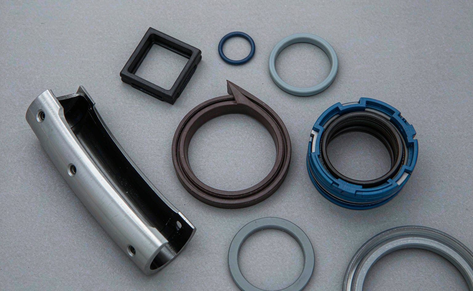
The profile determines how contact pressure is generated. Elastomer lips rely on interference plus air pressure; PTFE elements rely on a spring or elastomer energizer; integrated seal-and-guide designs trade one part number for tighter tolerances. The published pneumatic seal ranges from the major makers follow the same four families, which makes cross-referencing a worn part reasonably straightforward.
| Concept | Breakaway behaviour | Low-pressure sealing | Servizio migliore | Main risk |
|---|---|---|---|---|
| Elastomer lip (NBR or PU) | Highest; 10-25 N typical at 32 mm bore | Good once above 0.3 bar | General automation, 1-6 bar, moderate cycles | Stick-slip after long dwell |
| Short-contact lip profile (e.g. C2-type) | Moderate; reduced contact patch | Buono | Fast cycling, air-saving circuits | Sensitive to bore roundness and contamination |
| PTFE or filled-PTFE sliding element with elastomer energizer | Lowest elastomer option; minimal stiction | Requires energizer preload | Very low speed, oil-free air, clean rooms | Creep, wear, installation damage |
| Integrated seal and guide ring | Moderato | Buono | Short stroke, compact cylinders | Cannot replace separate bearing capacity under side load |
The short-contact profile is the most common upgrade for machines that already run at 4-6 bar and only need faster response. It reduces the sliding area without changing the compound, which is why it usually costs less than a PTFE conversion and requires no change to the piston groove.
Interference and Contact Width Set Breakaway Force
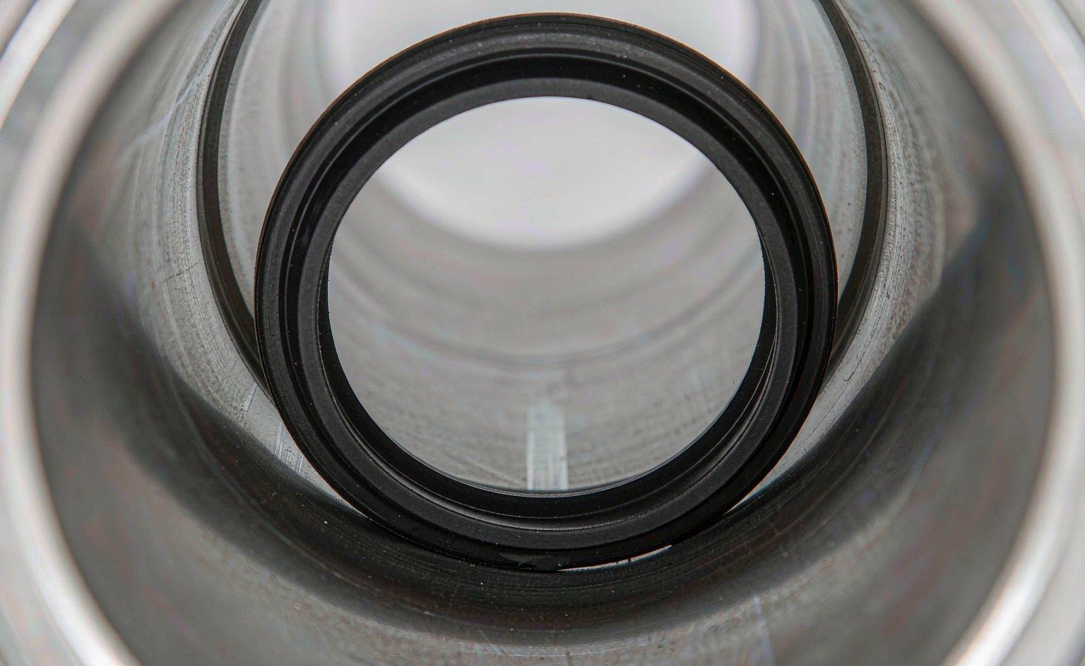
Friction force is roughly the product of contact pressure and contact area, plus the film shear term from whatever lubricant survives in the interface. In a pneumatic seal, contact pressure comes from radial interference — the amount by which the seal’s free outside diameter exceeds the bore.
Excess interference is the most common factory defect we see in aftermarket pneumatic seals. A seal moulded 0.15 mm over nominal will seal beautifully and make the cylinder feel sticky; the same seal at nominal will feel smooth and may weep at 0.2 bar. Neither behaviour shows up on a dimensional report unless the report includes the free-state diameter and the bore it is being measured against.
Three practical rules:
- Ask for the free-state radial interference, not just the groove and bore dimensions. It is the number that determines drag.
- Keep interference at the low end of the range when the cylinder runs at low pressure, and at the high end when the bore finish is rough or the air is wet.
- Never compensate for a worn bore by fitting an oversized seal. It buys a week of sealing and a month of stick-slip.
Bore and Rod Finish: The Multiplier Nobody Audits
Surface finish changes both friction and leakage, and it changes them in opposite directions. Too rough and the seal wears, the lubricant film breaks, and the cylinder leaks; too smooth and the surface cannot retain a film at all, so breakaway friction climbs and the seal chatters at low speed.
| Parameter | Target | Effect if out of range |
|---|---|---|
| Bore roughness Ra | 0.2-0.4 µm | Rougher: seal wear and leakage. Smoother: film starvation, higher stiction |
| Rod roughness Ra | 0.1-0.3 µm, hard chrome or ceramic | Rougher: wiper wear, contaminant ingress |
| Bore roundness | Within half the seal’s interference range | Oval bore concentrates contact on two arcs and doubles local pressure |
| Surface lay | Circumferential, no spiral or axial scores | Axial marks pump oil past the seal and cut the lip |
| Hard anodised layer | 25-50 µm, sealed | Thin or unsealed coating wears through and exposes aluminium oxide abrasive |
ISO 15552 sets mounting dimensions, not bore finish, so two cylinders that bolt up identically can seal very differently. Seal distributors’ technical libraries are useful here because they collect the counterface recommendations that cylinder catalogues usually leave out. If a customer reports that a seal works in one machine and not another with the same cylinder model, the bore is the first thing to measure, and the second is bore roundness at the port cross-hole, where the honing tool often leaves a low spot.
Lubrication: Oil-Free Air Is Not Grease-Free
Almost every pneumatic seal is assembled with a film of grease and then run on air that carries no oil. That initial charge is expected to last the life of the seal in a clean system, which is why the choice of assembly grease matters as much as the compound. A grease that migrates or oxidises leaves the lip dry within a few hundred thousand cycles, and dry running on an anodised bore is the fastest route to a polished, leaking seal.
Adding airline lubricant later is a commitment. Once oil is introduced it must be maintained continuously, because a seal that has swollen in oil will shrink and leak when the lubricator runs dry. Seal stockists see the aftermath of this pattern regularly: a cylinder that ran dry for two years, then received a lubricator as a “fix”, then leaked three months later. For food, pharmaceutical and semiconductor lines, oil-free operation is mandatory, and the correct answer is a PTFE-based element with a lubricant-retaining lip geometry rather than a low-friction elastomer running dry.
Hardness is a secondary lever here. A 90 Shore A NBR seal deforms less under the same interference and can reduce breakaway force slightly, but it also seals less well on a rough bore. In practice, changing durometer hardness by 5 points moves friction less than changing contact width by 0.2 mm.
Speed is the other half of the equation, and it has a floor. Below roughly 5 mm/s most elastomer-lip cylinders alternate between sticking and slipping, and the minimum stable speed depends on bore size: SMC rates selected low-speed cylinders to 0.5 mm/s, but assigns 1 mm/s to bores of 16 mm and smaller. If your application needs smooth motion at 1 mm/s in a 12 mm bore, no compound change will deliver it — the cylinder architecture has to change.
How to Measure Breakaway Force on a Real Cylinder
Catalogue friction figures are screening data, not acceptance criteria. Measure on the actual cylinder, with the actual air supply, at the pressure the machine will use.
- Mount the cylinder vertically or horizontally as installed, with the real load attached if possible.
- Fit a pressure gauge and a precision regulator at the cylinder port, not at the FRL unit.
- Slowly raise pressure from zero and record the pressure at which the rod first moves. That is breakaway.
- Repeat after a 10-minute dwell at rest, then after 1,000 cycles. Stick-slip shows up as a rising breakaway number across dwells.
- Then measure running friction: stroke at constant velocity and record the pressure differential between the two chambers.
- Test both directions. Extension and retraction have different effective areas and often different seal behaviour.
A useful acceptance target for a low-friction circuit is breakaway below 100 mbar at the working bore, and running friction stable within ±20% across the stroke. If breakaway climbs with dwell but running friction stays flat, you have a lubrication or compound problem. If both climb, look at bore finish and alignment first.
Writing the Specification
Most pneumatic seal specifications we receive list a hardness, a colour and a cylinder model. That is enough to quote a part and not enough to guarantee behaviour. The table below is the version that survives a second-source exercise.
| Line item | Example value | Why it matters |
|---|---|---|
| Seal type and profile | Piston lip seal, short contact, double-acting | Fixes the drag baseline before material is discussed |
| Compound and hardness | PU 92 Shore A, or NBR 70 Shore A, low-compression-set grade | PU resists abrasion; NBR is more forgiving on rough bores |
| Operating pressure range | 0.5-10 bar, per cylinder rating | Below 0.5 bar the seal must rely on interference alone |
| Intervallo di temperatura | -20 to +80 °C standard; -20 to +150 °C high-temp option | Standard ISO 15552 cylinders are rated -20 to +80 °C |
| Breakaway force | ≤ 100 mbar equivalent at 32 mm bore, after 10 min dwell | The only number that reflects real starting behaviour |
| Air quality | ISO 8573-1 class 3.4.3, or oil-free class 2.2.2 | Determines grease life and whether PTFE is required |
| Bore and rod finish | Ra 0.2-0.4 µm bore, Ra 0.1-0.3 µm rod | Half of all “bad seal” complaints are a finish complaint |
Two of those lines are unusual in a purchase order and both are worth the argument. Breakaway force is the only acceptance criterion that reflects what the machine actually does, and air quality determines whether the grease you assembled with will still be there in year three. A supplier who cannot discuss either number is selling parts, not sealing.
For cylinders where the seal and the guide share the load, the guide ring choice affects friction as much as the seal does: a worn or undersized wear band lets the piston tilt, which loads one side of the lip and doubles local contact pressure. Similarly, if the rod wiper is letting dust through, the piston seal is being asked to survive an abrasive that no compound is designed for — our note on seal failure patterns covers the visual signatures.
A Specification Checklist
Run through these before releasing a pneumatic seal drawing. Each line corresponds to a field failure we have seen more than once.
- State the lowest starting pressure, not the nominal supply. If the machine needs motion at 0.5 bar, the seal is a 0.5 bar seal.
- Convert force to friction. Divide the available thrust by the seal count — piston seal plus rod seal — and check that the result leaves margin for guide drag and load.
- Name the profile, not just the material. Short-contact lips and standard lips use the same compound and behave differently.
- Specify free-state interference and require it on the inspection report, alongside groove depth and bore diameter.
- Write the surface finish for bore and rod, and include roundness. A roughness callout alone lets an oval bore through.
- Define the air quality class and decide, in writing, whether the system is oil-free. Retrofitting a lubricator later invalidates the seal choice.
- Require a breakaway test at first article and after 1,000 cycles, with the dwell time stated.
- Check the guide before blaming the seal. Side load and bore ovality present as seal friction and seal leakage.
Most of the low-friction problems we are asked to solve turn out to be specification problems rather than compound problems. The pneumatic seal range covers lip seals, piston seals and complete kits in PU, NBR and filled PTFE, and the groove dimensions are interchangeable with the common ISO 15552 series; if you send the cylinder model and the force budget, we can tell you which profile fits before anyone cuts a mould. For static sealing inside the same cylinder — port seals, cushion seals, end-cap O-rings — a standard O-ring or X-ring in a 70 Shore A NBR is usually the right answer, provided the groove is sized for the pressure.